


Matrix Switch Modules 5
34980A User’s Guide 155
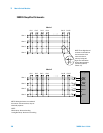
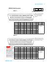
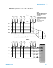
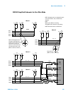
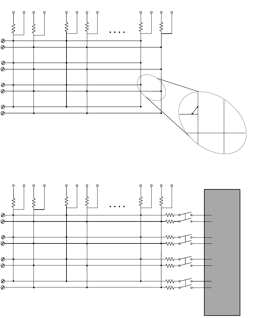
34933A Simplified Schematic for Two-Wire Mode
Row 8
Row 7
Row 6
922
923
924
921
H
H
H
H
L
L
L
L
C1L
C1L
bypass
L
C8H
C8H
bypass
H
C2L
C2L
bypass
L
C8L
bypass
L
C8L
H
L
L
L
L
H
H
H
C1H
C1H
bypass
H
C2H
C2H
bypass
H
ABus1
DMM
(MEAS)
ABus2
DMM
(SENS)
ABus3
ABus4
C2L
C2L
bypass
L
C8L
bypass
L
C8L
C2H
C2H
bypass
H
H
L
L
L
L
H
H
H
C1H
C1H
bypass
H
C1L
C1L
bypass
L
C8H
C8H
bypass
H
H
H
L
L
Row 1
Row 2
Row 3
Row 4
Row 5
Row 6
Row 7
Row 8
Matrix 1
Matrix 2
Col 1H Col 1L Col 2H Col 8H Col 8LCol 2L
Analog Buses
Col 1H Col 1L Col 2H Col 8H Col 8LCol 2L
NOTE: Three-digit channel numbers are derived from the intersection of
the rows and columns, columns having two digits. The intersection shown
here represents Channel 308 (Row 3, Column 8).
NOTE: Although columns are
numbered the same on the two
matrices, they are electrically
separate.
NOTE: Resistors shown
are 100
Ω each
NOTE:
Matrix relays: Reed non-latching
Analog Bus relays: Armature
non-latching