


4-Channel Isolated D/A Converter with Waveform Memory Module 9
34980A User’s Guide 187
The on-board memory provides storage for you to create up to 32 voltage or
current waveforms. You can apply a different waveform to each channel to
output. Or you can apply the same waveform to more than one channel. For
each channel you can designate the gain, frequency, and/or offset for its
output.
The waveforms are stored in volatile memory. Therefore, whenever power to
the 34980A is cycled, the volatile memory empties of data it has contained.
The waveform feature of the 34951A is not intended as a full-featured
substitute for a function generator, but as a means of storing point- to- point
updates.
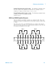
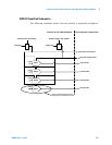
Clock In
You can configure each DAC channel on the module to synchronize off either
an internally- generated 20 MHz clock or the positive edge of an external
user-supplied clock.
An external clock must be less than 10 MHz or indeterminate behavior will
result. Additionally, as the maximum point- to-point update rate of the DACs
is 200 kHz, if you configure a DAC to run off an external clock, you will need
to ensure that the correct clock divisor is also configured for that DAC. For
example, if you supply a 10 MHz external clock, the minimum clock divisor is
50 because the maximum update rate is 200 kHz. If a clock divisor less than
the minimum is configured, indeterminate behavior will results. Thresholds
for the Clock In are 5 V TTL tolerant.
Clock Out
There is one clock output on the DAC module, which you can configure to
output at frequencies up to 10 MHz. Since it uses a 16-bit clock divisor, the
available output frequencies range in steps of 20 MHz/2
16
with a minimum
output frequency of 305 Hz. The output impedance of the Clock Out is 50 Ω.
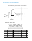
Trigger In
You can configure each DAC on the module to trigger off an externally
provide Trigger In that has a pulse width greater than 100 ns. The Trigger In
line is 5V TTL tolerant.
Trigger Out
The DAC module can source a TTL level Trigger Out. Trigger Out has a pulse
width between 5 and 10
µs.
NOTE
The line between external Clock Out and external Clock In is shared.
You can use the external Clock Out to provide the external Clock In
signal. However, both a user-supplied external clock and the
module’s Clock Out cannot drive the line at the same time.