


Features and Functions 2
34980A User’s Guide 31
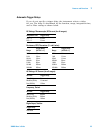
Thermocouple Measurements
• The instrument supports the following thermocouple types: B, E, J, K,
N, R, S, and T using ITS-90 software conversions. The default is a
J- Type thermocouple.
• Thermocouple measurements require a reference junction temperature.
For the reference junction temperature, you can use an internal
measurement on the module (34921A only), an external thermistor
or RTD measurement, or a known fixed junction temperature.
• The internal reference junction source is valid only on channels 1
through 40 on the 34921A with the 34921T terminal block installed.
• If you select an external reference, the instrument makes
thermocouple measurements relative to a previously- stored RTD or
thermistor measurement stored in a reference register. To store a
reference temperature, first configure a multiplexer channel for an
RTD or thermistor measurement. Then assign the measurement
from that channel as the external reference. When you initiate a
measurement on an external reference channel, the acquired
temperature is stored in volatile memory in the reference register.
Subsequent thermocouple measurements use the stored temperature
as their reference. The temperature remains in memory until you
measure a subsequent external reference value in the reference
register or remove the mainframe power.
• If you select a fixed reference temperature, specify a value between
-20 °C and +80 °C (always specify the temperature in °C regardless
of the temperature units currently selected).
• The accuracy of the measurement is highly dependent upon the
thermocouple connections and the type of reference junction used.
Use a fixed temperature reference for the highest accuracy
measurements (you must maintain the known junction temperature).
The internal isothermal block reference (34921A only) requires no
external wiring but provides lower accuracy measurements than a fixed
reference.
• The thermocouple check feature allows you to verify that your
thermocouples are properly connected for measurements. If you enable
this feature, the instrument measures the channel resistance after
each thermocouple measurement to ensure a proper connection. If an
open connection is detected (greater than 5 kΩ on the 10 kΩ range),
the instrument reports an overload condition for that channel
(or displays “OPEN T/C” on the front panel).