


16 34980A User’s Guide
2 Features and Functions
Measurement Functions
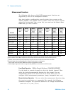
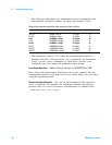
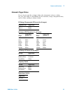
The following table shows which DMM measurement functions are
supported by each of the multiplexer modules.
Note that similar considerations must be taken into account on the
34931A, 34932A, and 34933A matrix modules. Since the matrix modules
cannot be incorporated into a scan list, you must use the Stand- Alone
DMM Mode for these modules.
Front Panel Operation: DMM or Channel (Configure) > DMM MEASUREMENT
Use the knob (or numeric keypad) to select the desired channel. Then
select the desired measurement function for this channel. You are
automatically guided to the next level of the menu where you can
configure other measurement parameters (range, integration time, etc.).
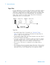
Remote Interface Operation: You can select the measurement function using
the
CONFigure and MEASure? commands. For example, the following
command configures the specified channel for dc voltage measurements.
CONF:VOLT:DC 10,DEF,(@3001)
Function
34921A
40-Ch Arm
MUX
34922A
70-Ch Arm
MUX
34923A
40-Ch Reed
MUX
(2-Wire)
34923A
80-Ch Reed
MUX
(1-Wire)
34924A
70-Ch Reed
MUX
34925A
40-Ch FET
MUX
(2-Wire)
34925A
80-Ch FET
MUX
(1-Wire)
Voltage, AC/DC Yes Yes Yes Yes Yes Yes Yes
Current, AC/DC Yes
1
No No No No No No
Frequency/Period Yes Yes Yes Yes Yes Yes Yes
Ohms 2-Wire Yes Yes Yes
5
Yes
5
Yes
5
Yes
6
Yes
6
Ohms 4-Wire Yes Yes Yes
5
No Yes
5
Yes
6
No
Thermocouple Yes
2
Yes
3
Yes
3,4
Yes
3,4
Yes
3,4
Yes
3
Yes
3
RTD 2-Wire Yes Yes Yes
5
Yes
5
Yes
5
No No
RTD 4-Wire Yes Yes Yes
5
No Yes
5
Yes
6
No
Thermistor Yes Yes Yes
5
Yes
5
Yes
5
No No
1
Direct current measurements are allowed on channels 41 through 44 only (for all other channels, external shunts are required).
2
Optional 34921T Terminal Block is required for thermocouple measurements with built-in internal reference junction.
3
A fixed or external reference junction temperature is required for thermocouple measurement with this module.
4
Impact of higher offset voltage specification (< 50 µV) must be taken into consideration.
5
1 kΩ or higher range used unless 100Ω series resistors are bypassed on module.
6
10 kΩ or higher range used for loads over approximately 300Ω due to series resistance of FET channels.