


164 34980A User’s Guide
6 General Purpose Switch Modules
General Purpose Switch Modules
Use the general-purpose (GP) switch modules in your 34980A mainframe to
route signals or control other system devices.
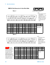
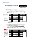
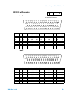
• The 34937A 32- Channel Form C and Form A GP Switch Module provides
independent control of 32 latching relays:
• Twenty-eight Form C relays rated for 1 A at 60 W per channel
• Four Form A relays rated for 5 A at 150 W per channel.
• For power switching applications, the 34938A 21-Channel 5 A Form A
Switch Module offers 20 Form A relays rated for 5 A at 150 W per channel.
Both modules contain armature-latching relays, and you can use these
switches for device actuation, digital output, or combined with other switch
modules to create flexible switching topologies. You can close multiple
channels at the same time. These modules do not connect to the analog
buses.
A temperature sensor on these modules triggers system interrupts when
high-carry current-induced heat on the modules is excessive and sets the
HOT annunciator on the front panel. This over- temperature situation
generates an SRQ event when the factory- set 70
o
C threshold is reached. It is
up to the user to determine what, if any, action should be taken.
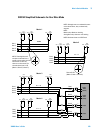
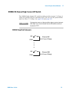
Reactive loads (those that include significant inductance or capacitance) can
cause voltage spikes or current spikes during switching operations. The
general purpose modules are designed for switching reactive loads. The
optional 34937T and 34938T terminal blocks have solder pads for adding
snubber circuits for the 5 A relays to reduce the reactive transients. See the
drawings on page 170 and page 173 for the locations of snubber circuit
pads and installation information about a snubber circuit.
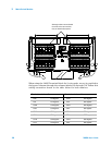
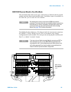
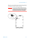
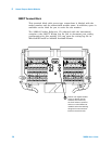
A hardware jumper on each of the GP modules allows you to define the
power-failure states for the modules’ 5 A latching relays. Depending on the
position of the jumper, the 5 A relays will either open or maintain state when
system power failure occurs. When shipped from the factory, the power-fail
jumper is in “MAINTAIN” position (all relays maintain their present state
when power fails).
NOTE
The 34937A has five 5 A relays, and the 34938A modules has 20
5 A relays
WARNING
Before changing the position of the jumper, remove external
connections from the module. Wait five to ten seconds to allow
the module’s internal capacitors to discharge.