


194 34980A User’s Guide
9 4-Channel Isolated D/A Converter with Waveform Memory Module
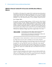
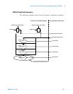
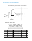
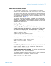
The following diagram shows individual DAC channel configuration.
All channels are configured the same.
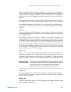
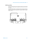
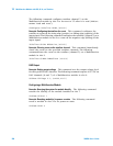
34951A D-Sub Connector Pinout
Each DAC is configured
as shown in this
drawing.
External
Clock
External
Trigger
Internal
Clock
Internal
Trigger
16 Bits
Waveform
Memory
HI Voltage Sense
LO Voltage Sense
HI Voltage, + Current
LO Voltage, − Current
DAC
x
Calibration constant in
non-volatile memory
Control Logic
Immediate
Data
25 mA resettable
thermal fuse
Internal to the 34951A Module User-Supplied Connections
34
35 36 37
38
39 40
41
42
43 44 45
46
47 48 49
50
GND GND GND GND GND GND GND GND GND GND GND GND GND GND GND GND GND
18
19
20 21 22 23 24 25 26 27 28 29 30 31 32 33
1234567891011121314151617
GNDGND NC 4 L 4H 3L 3H
GND GND
NC 2L 2H GND NC 1L 1H
GND
EXT
CLKGND
4L
Sense
4H
Sense GND TRIG GND
2L
Sense
2H
Sense
1L
Sense
1H
Sense
GND
3L
Sense
3H
Sense GND GND
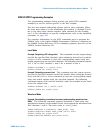
Description Pin Description Pin Description Pin Description Pin Description Pin
1L 15 3L Sense 21 GND 8 GND 34 GND 44
1H 16 3H Sense 22 GND 9 GND 35 GND 45
1L Sense 31 4L 3 GND 13 GND 36 GND 46
1H Sense 32 4H 4 GND 17 GND 37 GND 47
2L 11 4L Sense 19 GND 18 GND 38 GND 48
2H 12 4H Sense 20 GND 23 GND 39 GND 49
2L Sense 27External Clock24GND 26GND 40GND 50
2H Sense 28Trigger 25GND 29GND 41No Connect 2
3L 5GND 1GND 30GND 42No Connect 10
3H 6GND 7GND 33GND 43No Connect 14