


142 34980A User’s Guide
5 Matrix Switch Modules
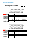
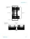
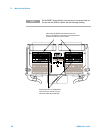
Linking Multiple Matrix Modules
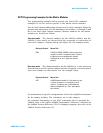
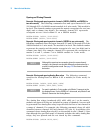
You can link multiple matrix modules to form a larger matrix. The following
two drawings show two-module connections through rows and columns.
Wiring Multiple 34931A or 34932A Modules
With a 34931A you can combine two matrices to form 8x8 (connecting
columns) or 4x16 (connecting rows) configurations. Using two 34932A
matrices on a 34932A module, you can create 16x8 (connecting columns) or
4x32 (connecting rows) configurations.
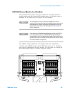
You can connect rows in separate modules using external wiring. Or, using
Bank 2 matrices, you can connect through the mainframe Analog Buses. For
a clear idea of how matrices are arranged and their connections to the
Analog Buses, see the simplified schematics on page 145 (34931A) and
page 150 (34932A).
You must use external wiring whenever you connect:
• Rows in Matrix 1 of separate modules
• Rows in Matrix 1 to rows in Matrix 2 on the same or separate modules
• Columns of two matrices on the same or separate modules
You can expand upon these two-module configurations and add up to eight
modules to design your own large matrices. From a programming standpoint,
each matrix module operates as an independent module regardless of the
external connections. When linking modules, the channel numbering scheme
remains the same as for single modules.
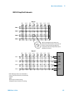
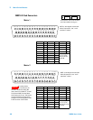
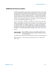
Wiring Multiple 34933A Modules
You can connect matrices on the 34933A module in a similar fashion to the
34931A. However, the presence of in-rush resistors on the Analog Buses and
columns require additional consideration, and you must take care when
linking multiple 34933A matrix modules. See the simplified schematics on
page 155 and page 159.