


Low Frequency Multiplexer Switch Modules 4
34980A User’s Guide 133
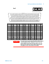
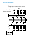
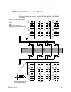
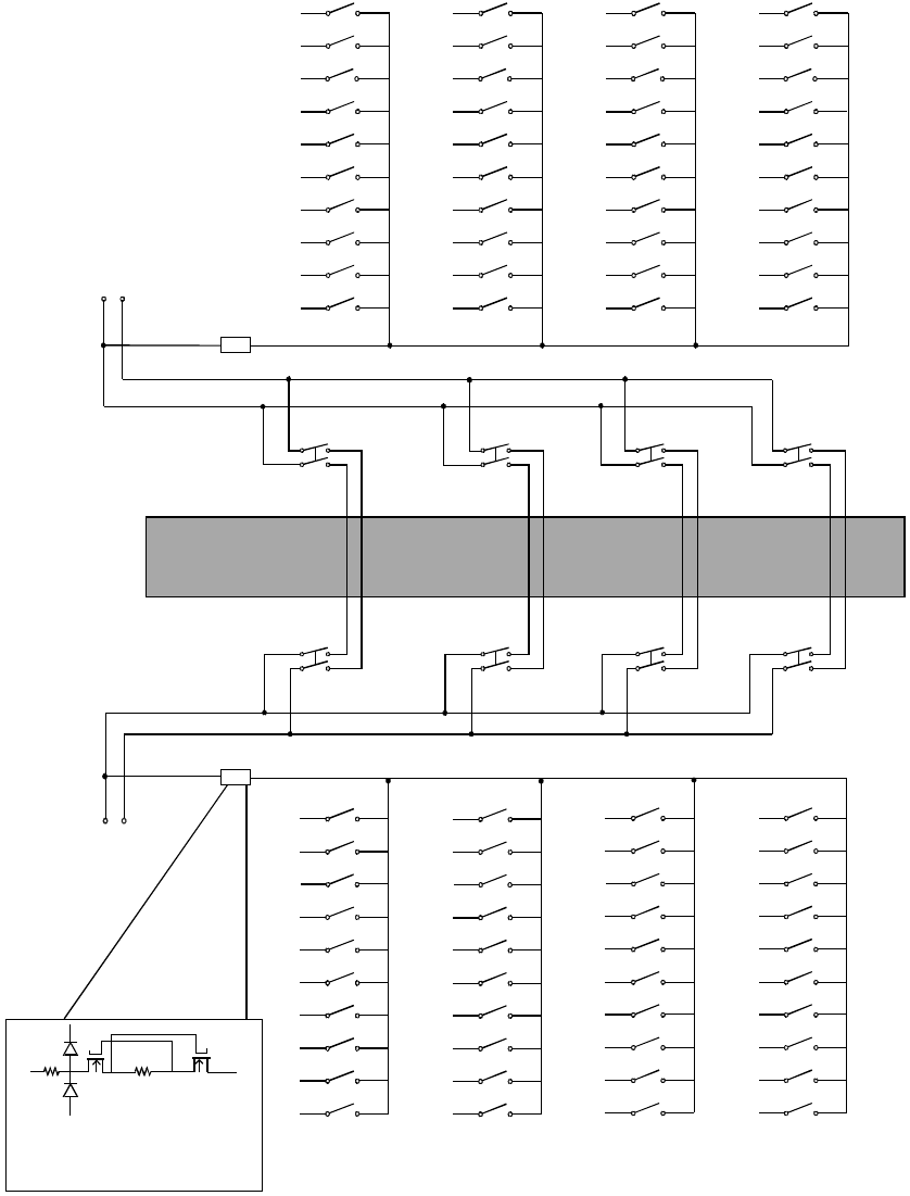
34925A Simplified Schematic for One-Wire Mode
This drawing shows two independent 40- channel, 1- wire MUXes. To
change configuration modes, use the SYSTem:MODule:WIRE:MODE
command.
HH
HHHH
ABus2
DMM
(SENS)
ABus3
ABus4
923
913
914
924
922
912
911
921
ABus1
DMM
(MEAS)
001
002
003
004
005
006
007
008
009
010
021
022
023
024
025
026
027
028
029
020
011
012
013
014
015
016
017
018
019
020
031
032
033
034
035
036
037
038
039
040
041
042
043
044
045
046
047
048
049
050
051
052
053
054
055
056
057
058
059
060
061
062
063
064
065
066
067
068
069
070
H
071
072
073
074
075
076
077
078
079
080
H
LHLH
LH
LH
LH
LH
LH
LH
LH
LH
Bank 1
Bank 2
COM 1
COM 2
Overvoltage protection and
current limiting circuitry
Analog Buses
NOTE: The three-digit number assigned
to each switch represents the channel
number.
NOTE:
Bank relays: FET non-latching
Analog Bus relays: Armature non-latching