


Low Frequency Multiplexer Switch Modules 4
34980A User’s Guide 123
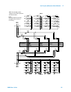
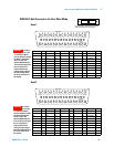
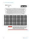
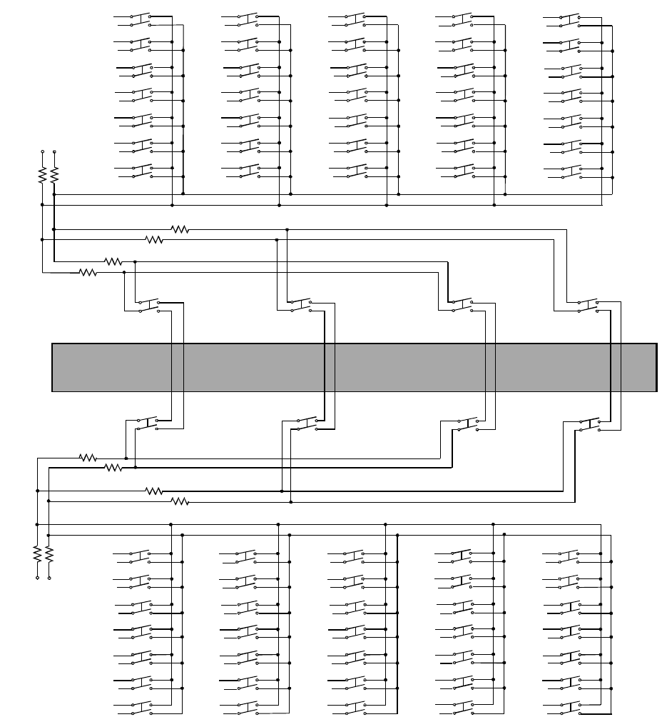
34924A Simplified Schematic
This drawing shows two independent 35- channel 2- wire MUXes.
ABus2
DMM
(SENS)
ABus3 ABus4
ABus1
DMM
(MEAS)
911 914912 913
924922 923921
LH
LH
001
002
003
004
005
H
L
006
H
015
016
017
018
019
L
020
021
022
023
024
025
026
H
L
027
028
029
030
031
032
033
H
L
034
008
009
010
011
012
H
L
013
007
035
014
H
L
036
037
038
039
040
041
042
H
L
043
044
045
046
047
048
049
H
L
050
051
052
053
054
055
056 063
H
L
064
065
066
067
068
069
070
057
058
059
060
061
062
H
L
LH
LH
LH
LH
LH
LHLH
LH
100Ω
100Ω
100Ω
100Ω
100Ω 100Ω
100Ω
100Ω
100Ω
100Ω 100Ω
100Ω
COM 1
COM 2
Analog Buses
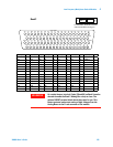
Bank 1
NOTE: The three-digit number assigned to each
switch represents the channel number.
Bank 2
NOTE:
Bank relays: Reed non-latching
Analog Bus relays: Armature non-latching