


Matrix Switch Modules 5
34980A User’s Guide 149
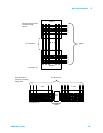
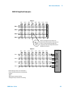
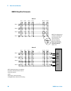
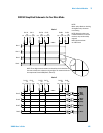
34932A Dual 4x16 Armature Matrix
The 34932A dual 4x16 armature matrix contains two matrices, each with 64
2-wire crosspoint latching armature relays organized in a 4-row by 16-column
configuration. Every row and column are made up of two wires each, a high
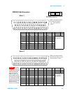
(H) and a low (L). Each crosspoint relay has a unique channel number
representing the row and column that intersect to create the crosspoint. For
example, channel 315 represents the crosspoint connection between row 3
and column 15 (all columns consisting of two digits; in this case the digits are
15). See the simplified schematic on page 150.
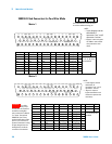
You can connect any combination of inputs and outputs at the same time.
However, only Matrix 2 in this module connects to the Analog Buses. By
closing channels 921 and 922 you can connect rows 5 and 6 respectively to
the internal DMM of the 34980A mainframe for voltage and resistance
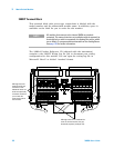
measurements. You can connect multiple matrix modules externally and/or
through the Analog Buses for applications that require large matrices. For
information on linking multiple matrix modules, refer to page 142 of this
chapter.
When the power is off, matrix relays maintain state, and Analog Bus
relays open.
NOTE
When the DMM is scanning, it controls ABus1 and ABus2 relays,
which are on Matrix 2. Therefore, consider this behavior when you
are connecting matrices.