


138 34980A User’s Guide
5 Matrix Switch Modules
Matrix Switch Modules
The matrix switch modules for the 34980A offer a convenient way for you to
connect multiple instruments to multiple points on your DUT. For a lower
cost and better specification alternative, you can connect both matrix and
multiplexer (MUX) modules.
Although flexible, it is possible to connect more than one source at the same
time with a matrix. Make sure that dangerous or unwanted conditions are
not created by these connections.
The family of matrix switch modules consists of:
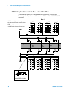
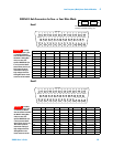
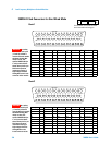
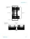
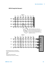
• the 34931A with two (dual) matrices of latching armature switches.
Each matrix is organized in a 4- row by 8-column configuration.
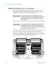
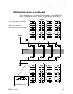
• the 34932A with two (dual) matrices of latching armature switches.
Each matrix is organized in a 4- row by 16-column configuration.
• the 34933A, with non-latching reed switches, which you can configure for:
• differential (2- wire) mode, which has two (dual) matrices.
Each matrix is organized in a 4- row by 8-column configuration.
• single- ended (1- wire) mode, which has four (quad) matrices.
Each matrix is organized in a 4- row by 8-column configuration.
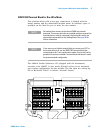
NOTE
Safety Interlock Analog Buses of the 34980A can carry 300 V
signals. MUX and matrix modules with Analog Bus relays have a
hardware Safety Interlock feature that forces Analog Bus relays
open when their associated D-sub connector (faceplate) interlock
pins lose continuity. This prevents signals from the Analog Buses
from being present on D-sub connector pins. Optional Agilent
terminal blocks automatically provide continuity for the interlock
pins. When the terminal blocks are not used, you must provide
continuity for the interlock pins in the DUT assembly. See pinout
drawings and tables in this chapter for the location of interlock pins
on the module of interest.
Matrix modules have Analog Bus relays on Bank 2 only, and thus,
have interlock pins on only their Bank 2 connectors.
Normally, if you attempt to connect to the Analog Buses without a
terminal block or cable connected, an error is generated. The
SYSTem:ABUS:INTerlock:SIMulate command allows
you to temporarily disable errors generated by the Safety Interlock
feature and enables the Safety Interlock simulation mode. Although
Safety Interlock errors are suppressed in this mode, the actual
Analog Bus relays affected by the Safety Interlock are disabled as
long as no terminal block or cable is connected to the module.