


Introduction to the Plug-In Modules for the 34980A 3
34980A User’s Guide 93
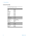
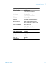
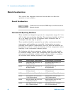
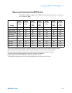
Electrical Operating Conditions
34937A 28 channels, 300 V rms or DC,
1 A, 60 VA per channel
4 channels, 250 V rms or 30 VDC,
5A, 150 VA per channel
28 channels, 100 V rms or DC,
1 A, 60 VA per channel
4 channels, 100 V rms or 30 VDC,
5A, 150 VA per channel
34938A 20 channels, 250 V rms or 30 VDC,
5 A, 150 VA per channel
20 channels, 100 V rms or 30 VDC,
5 A, 150 VA per channel
34941A Four channels, 30 V, 0.5 A,
10 W per channel
Four channels, 30 V, 0.5 A,
10 W per channel
34946A Dual channel, 7 V, 1 W per channel,
4 GHz or 20 GHz
Dual channel, 7 V, 1 W per channel, 4
GHz or 20 GHz
34947A Triple channel, 7 V, 1 W per channel,
4 GHz or 20 GHz
Triple channel, 7 V, 1 W per channel,
4 GHz or 20 GHz
34951A 4 channels, 16 V, 20 mA 4 channels, 16 V, 20 mA
34952A 32 DIO channels, 42 V, 400 mA,
2 channel DAC, 12 V, 10 mA
32 DIO channels, 42 V, 400 mA,
2 channel DAC, 12 V, 10 mA
NOTE
Pollution Degree 1: No pollution or only dry, non-conductive pollution
occurs. The pollution has no influence (on insulation) (IEC 61010-1
2nd Edition).
NOTE
Pollution Degree 2: Normally only non-conductive pollution occurs.
Occasionally, a temporary conductivity (leakage current between
isolated conductors) caused by condensation can be expected (IEC
61010-1 2nd Edition).
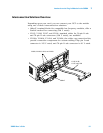
CAUTION
For proper module cooling, all unused slots must be covered.
Module Pollution Degree 1 Specifications Pollution Degree 2 Specifications
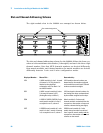
WARNING
To avoid electric shock, turn off the 34980A and disconnect or
de-energize all field wiring to the modules and the Analog Bus
connector before removing any module or slot cover.