


130 34980A User’s Guide
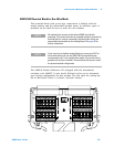
4 Low Frequency Multiplexer Switch Modules
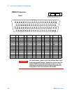
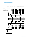
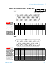
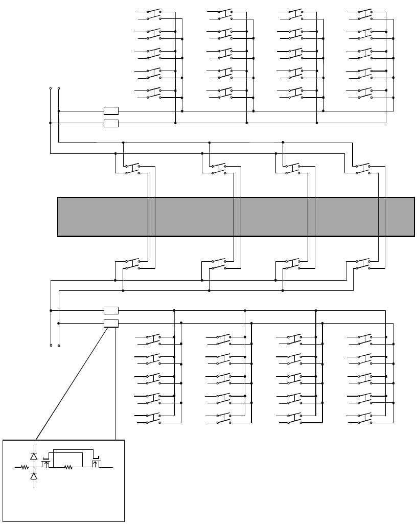
34925A Simplified Schematic for Two- or Four-Wire Mode
This drawing shows two independent 20- channel 2-wire MUXes.
To change configuration modes, use the SYSTem:MODule:WIRE:MODE
command.
026
027
028
029
030
031
032
033
034
035
036
037
038
039
040
021
022
023
024
025
001
002
003
004
005
006
007
008
009
010
011
012
013
014
015
016
017
018
019
020
H
L
H
L
H
L
H
L
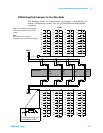
ABus2
DMM
(SENS)
ABus3
ABus4
923
913 914
924922
912911
921
ABus1
DMM
(MEAS)
H
L
H
L
H
L
H
L
LH
LH
LHLHLHLH
LHLHLH
LH
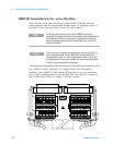
Overvoltage protection and
current limiting circuitry
COM 1
Bank 2
COM 2
Analog Buses
Bank 1
NOTE: The three-digit number assigned to
each switch represents the channel number.
NOTE:
Bank relays: FET non-latching
Analog Bus relays: Armature non-latching