


Low Frequency Multiplexer Switch Modules 4
34980A User’s Guide 121
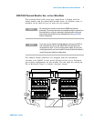
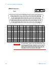
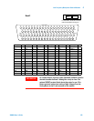
34924A 70-Channel Reed Multiplexer
The high-density 34924A 70-Channel Reed Multiplexer (70-Ch Reed
MUX) is divided into two banks with 35 non-latching reed switches
(channels 1-35 and 36-70) in each. This module also contains eight
armature Analog Bus relays (channels 911-914 and 921-924), four on
each bank that can connect the bank relays to the system Analog Buses.
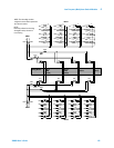
Through ABus1 and ABus2 you can connect any of the channels to the
system DMM for voltage or resistance measurements. See the simplified
schematic on page 123.
Using program commands or the mainframe front panel, you can control
each of the channel switches individually, and thus configure this module
in the modes listed below.
• two independent 35- channel 2-wire MUXes. This configuration
requires neither using external wiring nor connecting through the
internal Analog Buses.
• one 70-channel, 2- wire MUX. You must use external wiring or connect
through the internal Analog Buses for this configuration.
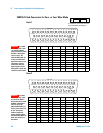
• one 35- channel 4-wire MUX. This configuration requires neither using
external wiring nor connecting through the internal Analog Buses. For
4-wire resistance measurements, the instrument automatically pairs
channel n on Bank 1 with channel n+35 (Bank 2) to provide the
source and sense connections. Four-wire controls occur only when
doing 4-wire measurement operations through the internal DMM, such
as MEASure:FRESistance? or scanning a channel previously
configured as 4- wire.
In 2-wire mode, you can close no more than 20 channels simultaneously
due to power dissipation. These 20 channels are split 10 to a bank.
However, note that Analog Bus relays count half as much as channel
relays in that total. For example, with one Analog Bus relay closed, you
can close up to a maximum of 19 channel relays. If you try to close more
than the allowed number of channels, you will receive an error message.
In all modes, this module has capability to scan as many as 500
channels/second using the internal DMM. With the automatic
“break-before-make” connection operation, you are assured that no two
signals are connect to each other during a scan.
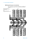
CAUTION
Because user-attached reactive loads and backplane parasitic
capacitance may result in high in-rush currents, 100 Ω in-rush
resistors protect the reed relays from damage and performance
degradation. Therefore, you must consider these resistors when
you are designing a measurement. Refer to the simplified schematic
on page 123.