


96 34980A User’s Guide
4 Low Frequency Multiplexer Switch Modules
Low Frequency Multiplexer Switch Modules
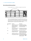
All low frequency multiplexer (MUX) switch modules feature two banks
of channels that provide broad multiplexing and measuring capabilities.
You can connect a MUX to an external instrument, and/or switch
multiple analog signals to the internal DMM. With the 34921A, 34922A,
34923A, and the 34924A modules, you can close more than one channel
in each bank simultaneously (N:1 configuration). As the 34925A module
is protected with overvoltage circuitry, you can close only one channel in
each bank at one time (1:N configuration).
And, you can connect multiple MUXes to the built-in Analog Buses,
which allow you to scan as many as 560 2-wire (differential) channels or
640 1-wire (single-ended) channels in one 34980A mainframe.
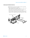
NOTE
Safety Interlock Analog Buses of the 34980A can carry 300 V
signals. MUX and matrix modules with Analog Bus relays have a
hardware Safety Interlock feature that forces Analog Bus relays
open when their associated D-sub connector (faceplate) interlock
pins lose continuity. This prevents signals from the Analog Buses
from being present on D-sub connector pins. Optional Agilent
terminal blocks automatically provide continuity for the interlock
pins. When the terminal blocks are not used, you must provide
continuity for the interlock pins in the DUT assembly. See pinout
drawings and tables in this chapter for the location of interlock pins
on the module of interest.
MUX modules with Analog Bus connections have Analog Bus
relays on each of their two banks. Therefore, the interlock pins are
found on both Bank 1 and Bank 2 D-sub connectors of the MUX
modules.
Normally, if you attempt to connect to the Analog Buses without a
terminal block or cable connected, an error is generated. The
SYSTem:ABUS:INTerlock:SIMulate command allows
you to temporarily disable errors generated by the Safety Interlock
feature and enables the Safety Interlock simulation mode. Although
Safety Interlock errors are suppressed in this mode, the actual
Analog Bus relays affected by the Safety Interlock are disabled as
long as no terminal block or cable is connected to the module.