


154 34980A User’s Guide
5 Matrix Switch Modules
One-Wire Mode
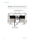
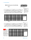
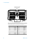
To physically configure the module in 1-wire mode, use the 34933T-002
terminal block, or a compatible standard or custom cable. If using a standard
or custom cable, make sure you connect interlock pins 17 and 33 on the
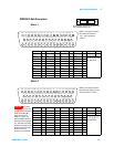
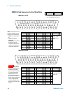
Matrix 2 D-sub connector. Refer to the pinout drawing and table on
page 160.
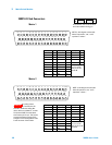
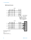
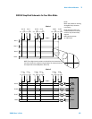
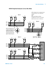
In 1-wire mode, the 34933A module contains four matrices (1 through 4),
each with 32 1-wire crosspoint non- latching reed relays organized in a 4-row
by 8-column configuration. Every row and column has one wire each. Each
crosspoint relay has a unique channel number representing the matrix, and
the single-wire row and column that intersect to make the crosspoint. For
example, channel 218 represents Matrix 2, row 1 and column 8. See the
simplified schematic on page 159.
In 1- wire mode, you can close no more than 40 channels simultaneously due
to power dissipation. For example, with one Analog Bus relay closed you can
close up to a maximum of 39 channel relays. If you try to close more than the
allowed number of channels, you will receive an error message.
You can connect any combination of inputs and outputs at the same time.
However, only Matrix 3 and Matrix 4 in 1-wire mode of this module connect
to the Analog Buses. By closing channels 921 and 922 you can connect rows 1
and rows 2 respectively to the internal DMM of the 34980A mainframe for
voltage and resistance measurements.
You can connect multiple matrix modules externally and/or through the
Analog Buses for applications that require large matrices. For information on
linking multiple matrix modules, refer to page 142 of this chapter.
When the power is off, matrix relays and Analog Bus relays open.