


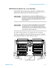

Low Frequency Multiplexer Switch Modules 4
34980A User’s Guide 113
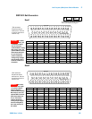
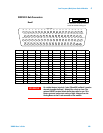
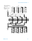
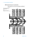
Four-Wire Mode
This 20-channel 4- wire MUX This configuration requires neither using
external wiring nor connecting through the internal Analog Buses. For
4-wire resistance measurements, the instrument automatically pairs
channel n on Bank 1 with channel n +20 (Bank 2) to provide the source
and sense connections. Four-wire controls occur only when doing 4-wire
measurement operations through the internal DMM, such as
MEASure:FRESistance? or scanning a channel previously configured as
4- wire.
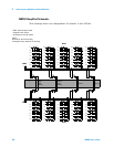
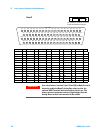
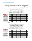
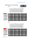
One-Wire Mode
• two independent 40- channel 1-wire MUXes. This configuration
requires neither using external wiring nor connecting through the
internal Analog Buses.
• one 80- channel 1- wire MUX. You must use external wiring or connect
through the internal Analog Bus for this configuration.
In 1-wire mode, you can close no more than 40 channels simultaneously
due to power dissipation. These channels are split 20 to a bank. For
example, with one Analog Bus relay closed you can close up to a
maximum of 39 channel relays. If you try to close more than the allowed
number of channels, you will receive an error message.
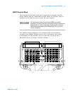
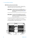
In all modes, this module has capability to scan as many as 500
channels/second using the internal DMM. With the automatic
“break-before-make” connection operation, you are assured that no two
signals are connect to each other during a scan.
This module is interlock protected, which means whenever the D- sub
connector end of the modules is exposed, the Analog Bus relays
immediately open and disconnect from the Analog Bus. For more
information, refer to page 96, and page 116 or page 119.
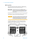
NOTE
Because all bank relays supply only HI signals, you can apply a
LOW signal through COM1 L or COM2 L when you are making
2-wire resistance measurements in 1-wire mode.
CAUTION
Because user-attached reactive loads and backplane parasitic
capacitance may result in high in-rush currents, 100
Ω in-rush
resistors protect the reed relays from damage and performance
degradation. Therefore, you must consider these resistors when
you are designing a measurement. Refer to the simplified
schematics on page 114 and page 118.