


102 34980A User’s Guide
4 Low Frequency Multiplexer Switch Modules
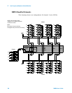
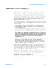
34921A 40-Channel Armature Multiplexer with Low Thermal Offset
The 34921A 40-Channel Armature Multiplexer (40-Ch Arm MUX) is
divided into two banks with 20 latching armature switches (channels
1-20 and 21-40) in each. This module also offers four additional fused
relays (channels 41-44) for making AC and DC current measurements
with the internal DMM with no external shunts needed. These current
channels feature “make-before-break” connections to ensure continuous
current flow when switching from one current channel to another.
The current fuses are replaceable. Refer to the 34980A Service Guide for
specific information about these fuses.
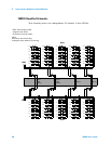
This module also contains nine armature Analog Bus relays (channels
911-914, 921-924, and 931), four on each bank that can connect the bank
relays to the system Analog Buses and one that connects the current
relays to the current input of the DMM. Through ABus1 and ABus2 you
can connect any of the channels to the internal DMM for voltage or
resistance measurements. Refer to the simplified schematic on page 104.
Using program commands or the mainframe front panel, you can control
each of the channel switches individually, and thus configure this module
in these modes:
• two independent 20-channel 2- wire MUXes. This configuration
requires neither using external wiring nor connecting through the
internal Analog Buses.
• one 20-channel 4- wire MUX. This configuration requires neither using
external wiring nor connecting through the internal Analog Buses.
For 4-wire resistance measurements, the instrument automatically
pairs channel n on Bank 1 with channel n+20 (Bank 2) to provide the
source and sense connections. Four-wire controls occur only when
doing 4-wire measurement operations through the internal DMM, such
as MEASure:FRESistance? or scanning a channel previously
configured as 4-wire.
• one 40-channel 2-wire MUX. You must use external wiring or connect
through the internal Analog Bus relays for this configuration. For
example, closing Analog Bus channels 913 and 923 connects Bank 1
and Bank 2 through ABus3. Or, externally you can connect COM1 to
COM2 to create this configuration.
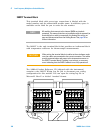
NOTE
ABus1 consists of three wires that are used for current and voltage
measurements. You cannot measure current and voltage on ABus1
simultaneously.