


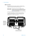
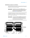

Matrix Switch Modules 5
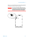
34980A User’s Guide 159
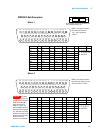
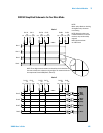
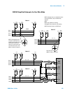
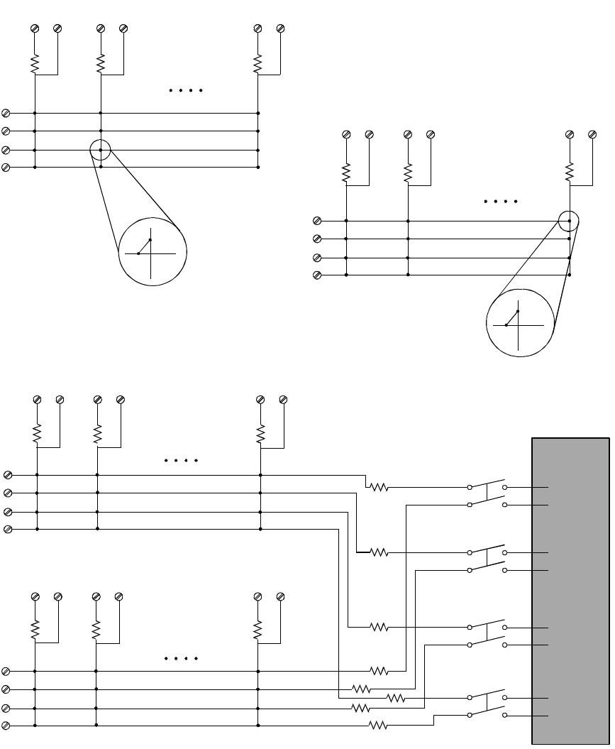
34933A Simplified Schematic for One-Wire Mode
H
H
H
H
H
H
1C2
1C2
bypass 1C8
1C8
bypass
1C1
1C1
bypass
L
L
2C8
bypass
2C8
2C1
2C1
bypass
2C2
2C2
bypass
L
L
L
L
921
922
923
924
H
H
L
L
H
H
L
L
H
H
H
H
3C2
3C1
3C1
bypass
3C2
bypass
3C8
3C8
bypass
4C1
4C1
bypass
4C2
4C2
bypass
4C8
4C8
bypass
L
L
L
L
ABus1
DMM
(MEAS)
ABus2
DMM
(SENS)
ABus3
ABus4
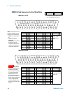
Row 1
Row 3
Row 4
Row 2
NOTE:
Matrix relays: Reed non-latching
Analog Bus relays: Armature non-latching
Row 1
Row 3
Row 4
Row 2
Matrix 1
NOTE: Although rows are numbered the same
across the matrices, they are electrically
separate.
NOTE: Three-digit channel
numbers are derived from a
specific matrix number and the
intersection of rows and
columns on that matrix. The
channel shown here is 132
(Matrix 1, Row 3, Column 2.)
Channel 2128
(Matrix 2, Row 1, Column 8)
NOTE: Resistors shown are 100
Ω each
Row 1
Row 3
Row 4
Row 2
Row 2
Row 1
Row 1
Row 2
Row 3
Row 3
Row 4
Row 4
Analog Buses
Row 1
Row 3
Row 4
Row 2
Matrix 2
Matrix 3
Matrix 4