


Chapter 2 Product Overview
12 Reference Manual XTX 820
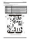
Connector Definitions
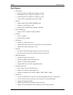
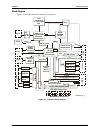
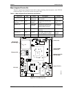
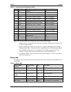
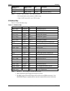
Table 2-2 describes the connectors shown in Figures 2-4 and 2-5.
Table 2-2. Board Connector Descriptions
No. Signals Description
J1 PCI, USB, Audio 100-pin connector for 32-bit PCI, USB (4 ports), and Audio
J2 PCI Express, SATA 100-pin connector for PCI Express, 2x SATA, USB (2 ports), LPC,
ExpressCards (2), AC'97/HDA Audio, extended system management
J3 Video, I/O 100-pin connector for Video (VGA, LVDS) and I/O (Floppy/Parallel,
Serial Ports 1 & 2, and Infrared) signals
J4 IDE, Ethernet
100-pin connector for IDE (Primary & Secondary IDE), I
2
C bus,
Power Management, and the Ethernet port
J5 DDR2 Memory 200-pin socket for a DDR2 SODIMM RAM
J6 SDVO port 45-pin Serial Digital Video Output ports (2)
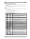
U30
U25
U28
U17
J6
U21
J1 J2
J3
J4
PCI, USB, Audio (J1) PCI Express, SATA (J2)
Video, I/O (J3) IDE, Ethernet (J4)
SDVO
(J6)
Flash
(U30)
Audio
CODEC
(U21)
XTX820_02a
Figure 2-5. Connector Locations (Bottom view)