


Chapter 3 Hardware
54 Reference Manual XTX 820
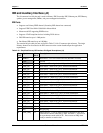
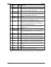
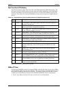
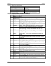
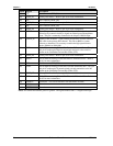
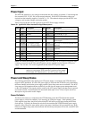
Pin # Signal Description
83 NC Not Connected (SIDE_D9)
84 PIDE_D5 Primary Disk Data 5 – Refer to pin-58 for more information.
85 NC Not Connected (SIDE_D6)
86 PIDE_D9 Primary Disk Data 9 – Refer to pin-58 for more information.
87 NC Not Connected (SIDE_D8)
88 PIDE_D6 Primary Disk Data 6 – Refer to pin-58 for more information.
89 GPE2* General Purpose Power Management Event Input 2. This signal may be
driven low by external circuitry to signal an external power management
event. This pin is commonly connected to the chipset’s RING# input.
90 CBLID_P*
Primary Cable ID Select – Used to detect the presence of an 80 conductor
IDE cable on the primary IDE channel. This allows BIOS or system
software to determine if is necessary to enable the high-speed transfer
modes (DMA66 or DMA100).
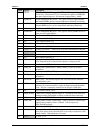
91 RXD- Half of Ethernet Analog Twisted Pair Receive Differential Pair – This pin
and pin-93 make up the Receive twisted pair and receive the serial bit
stream on the Unshielded Twisted Pair Cable (UTP).
92 PIDE_D8 Primary Disk Data 8 – Refer to pin-58 for more information.
93 RXD+ Half of Ethernet Analog Twisted Pair Receive Differential Pair – Refer to
pin-91 for more information.
94 NC Not Connected (SIDE_D7)
95 TXD- Half of Ethernet Analog Twisted Pair Transmit Differential Pair – This pin
and pin-97 make up the Transmit twisted pair and transmit the serial bit
stream on the Unshielded Twisted Pair Cable (UTP).
96 PIDE_D7 Primary Disk Data 7 – Refer to pin-58 for more information.
97 TXD+
Half of Ethernet Analog Twisted Pair Transmit Differential Pair – Refer to
pin-95 for more information.
98 HDRST* Hard Reset – Low active hardware reset (RSTDRV inverted)
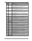
99 GND6
Ground
100 GND8
Ground
Notes: The shaded area denotes power or ground. The signals marked with * = Negative true logic.