


Chapter 3 Hardware
XTX 820 Reference Manual 21
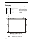
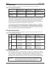
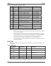
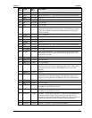
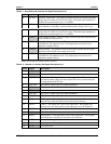
J1
Pin #
Signal PCI
Pin #
Description
43 AD13 46 (A46) Address/Data bus 13 – Refer to Pin-20 (A20) for more information
39 AD11 47 (A47) Address/Data bus 11 – Refer to Pin-20 (A20) for more information
GND 48 (A48) Ground
34 AD9 49 (A49) Address/Data bus 9 – Refer to Pin-20 (A20) for more information
NC Key 50 (A50) +5 Volt Key
NC Key 51 (A51) +5 Volt Key
31 CBE0* 52 (A52)
PCI Bus Command/Byte Enable 0 – This signal line is one of four
signal lines multiplexed on the same pins, so that during the address
cycle, the command is defined and during the data cycle, the byte
enable is defined.
+3.3V 53 (A53) +3.3 Volt Power
29 AD6 54 (A54) Address/Data bus 06 – Refer to Pin-20 (A20) for more information
27 AD4 55 (A55) Address/Data bus 04 – Refer to Pin-20 (A20) for more information
Ground 56 (A56) Ground
26 AD2 57 (A57) Address/Data bus 02 – Refer to Pin-20 (A20) for more information
23 AD0 58 (A58) Address/Data bus 00 – Refer to Pin-20 (A20) for more information
+3.3V(I/O) 59 (A59) +3.3V I/O
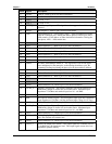
NC REQ64* 60 (A60)
Request 64-bit Transfer – This signal, when asserted by the current
bus master, indicates it desires to transfer data using 64 bits. Not
used in 32-bit system.
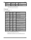
NC +5V 61 (A61) +5 Volt Power
NC +5V 62 (A62) +5 Volt Power
NC -12V 63 (B1) -12 Volt Power
NC TCK 64 (B2) Test Clock – This signal is used to clock state information and test
data into and out of the device during operation of the TAP. One of
five pins used for the optional JTAG/Boundary Scan and TAP
function.
Ground 65 (B3) Ground
NC TDO 66 (B4) Test Output – This signal is used to serially shift test data and test
instructions out of the device during TAP operation. One of five
pins used for the optional JTAG/Boundary Scan and TAP function.
NC +5V 67 (B5) +5 Volt Power
NC +5V 68 (B6) +5 Volt Power
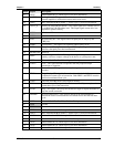
98 INTB* 69 (B7)
Interrupt B – This signal is used to request an interrupt and only has
meaning on a multi-function device.
96 INTD* 70 (B8) Interrupt D – This signal is used to request an interrupt and only has
meaning on a multi-function device.
NC PRSNT1* 71 (B9) Present 1 – These signals (Present 1::2) indicate to the motherboard
if an add-in board is physically present in the slot and, if one is
present, the total power requirements of the board. These signals are
required for add-in boards but are optional for motherboards.
Reserved 72 (B10) Reserved
NC PRSNT2* 73 (B11) Present 2 – See pin-71 (B9) for more information.