


Chapter 3 Hardware
30 Reference Manual XTX 820
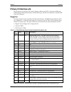
Serial ATA
The I/O Hub (82801FBM) provides two Serial ATA150 connections through the J2 connector. Serial
ATA is an enhancement of parallel ATA, but is not limited by the traditional restrictions of parallel
ATA. Serial ATA has higher performance characteristics with respect to speed and EMV. Serial ATA
starts with a transfer rate of 150 Mbytes/s as compared to the legacy Parallel ATA devices that were
limited to ATA133 (133MHz) or slower (33/66/100 MHz). In the future, it is hoped that SATA can be
expanded up to 600 Mbytes/s to accommodate future advanced developments. Serial ATA is
completely protocol and software compatible to parallel ATA.
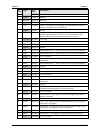
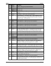
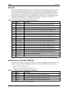
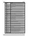
Table 3-10. Serial ATA Interface Pin/Signal Descriptions (J2)
Pin # Signal Description
4 SATA0_RX+ Serial ATA Channel 0, Receive Input, Positive Differential Line
6 SATA0_RX- Serial ATA Channel 0, Receive Input, Negative Differential Line
12 SATA0_TX+ Serial ATA Channel 0, Transmit Output, Positive Differential Line
10 SATA0_TX- Serial ATA Channel 0, Transmit Output, Negative Differential Line
16 SATA1_RX+ Serial ATA Channel 1, Receive Input, Positive Differential Line
18 SATA1_RX- Serial ATA Channel 1, Receive Input, Negative Differential Line
24 SATA1_TX+ Serial ATA Channel 1, Transmit Output, Positive Differential Line
22 SATA1_TX- Serial ATA Channel 1, Transmit Output, Negative Differential Line
28 SATA2_RX+ Serial ATA Channel 2, Receive Input, Positive Differential Line
30 SATA2_RX- Serial ATA Channel 2, Receive Input, Negative Differential Line
40 SATA2_TX+ Serial ATA Channel 2, Transmit Output, Positive Differential Line
38 SATA2_TX- Serial ATA Channel 2, Transmit Output, Negative Differential Line
44 SATA3_RX+ Serial ATA Channel 3, Receive Input, Positive Differential Line
46 SATA3_RX- Serial ATA Channel 3, Receive Input, Negative Differential Line
54 SATA3_TX- Serial ATA Channel 3, Transmit Output, Negative Differential Line
56 SATA3_TX+ Serial ATA Channel 3, Transmit Output, Positive Differential Line
58 IL_SATA* Serial ATA Interlock Switch Input
50 SATALED* Serial ATA Activity LED
Notes: The shaded area denotes power or ground. The signals marked with * = Negative true logic
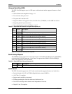
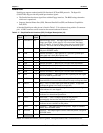
Additional Universal Serial Bus (USB) Ports
The J2 connector supports two additional USB ports for a total of six USB ports for the baseboard. The
features for these two additional USB ports are the same as the four USB ports on the J1 connector.
• Supports USB v2.0 and legacy v.1.1
• Supports one root hub for these two ports on (J2)
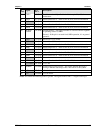
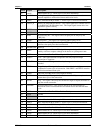
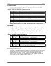
Table 3-11. USB 4 & 5 Interface Pin/Signal Descriptions (J2)
Pin # Signal Description
45 USBP4+ Universal Serial Bus Port 4, Positive Differential Line
47 USBP4- Universal Serial Bus Port 4, Negative Differential Line
25 USBP5+ Universal Serial Bus Port 5, Positive Differential Line
27 USBP5- Universal Serial Bus Port 5, Negative Differential Line
Note: The shaded area denotes power or ground.