


Chapter 3 Hardware
XTX 820 Reference Manual 45
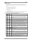
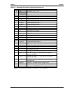
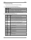
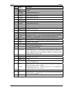
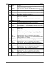
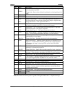
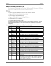
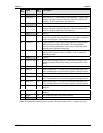
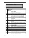
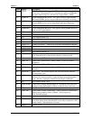
Pin # Signal Description
80 PD0
INDEX*
Parallel Port Data 0 – This pin (0 to 7) provides a parallel port data signal
and is the printer data LSB.
Floppy Index –Detects when the head is positioned over the beginning of the
track.
81, 82 VCC DC Power – +5V +/- 5%
83 RXD1 Receive Data 1 – Serial port 1 receive data in.
84 ACK*
DRV*
Parallel Acknowledge * – This is a status input signal from the printer. A
Low State indicates it has received the data and is ready to accept new data.
Floppy Drive Select 1 – This signal selects drive 1.
85 RTS1* Request To Send 1 – Indicates Serial port 1 is ready to transmit data. Used
as hardware handshake with CTS1 for low level flow control.
86 BUSY
MOT*
Parallel Busy – This is a status input signal from the printer. A high state
indicates the printer is not ready to accept data.
Floppy Motor Control 1 – This signal selects motor on drive 1.
87 DTR1* Data Terminal Ready 1 – Indicates Serial port 1 is powered, initialized, and
ready. Used as hardware handshake with DSR1 for overall readiness.
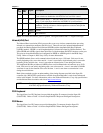
88 PE
WDATA*
Parallel Paper End – This is a status input signal from the printer. A high
state indicates it is out of paper.
Floppy Write Data – Encoded data to the drive for write operations.
89 DCD1* Data Carrier Detect 1 – Indicates external serial device is detecting a carrier
signal (i.e., a communication channel is currently open). In direct connect
environments, this input is driven by DTR1 as part of the DTR1/DSR1
handshake.
90 SLCT*
WGATE*
Parallel Select – This is a status output signal from the printer. A high state
indicates it is selected and powered on.
Floppy Write Gate – Signals drive to enable current flow in the write head.
91 DSR1* Data Set Ready 1 – Indicates external serial device is powered, initialized,
and ready. Used as hardware handshake with DTR1 for overall readiness.
92 MSCLK Mouse Clock – This signal clocks the data from the mouse.
93 CTS1* Clear To Send 1 – Indicates external serial device is ready to receive data.
Used as hardware handshake with RTS1 for low level flow control.
94 MSDAT Mouse Data – This signal provides the mouse data.
95 TXD1 Transmit Data 1 – Serial port 1 transmit data out
96 KBCLK Keyboard Clock – This signal clocks the data from the keyboard.
97 RI1* Ring Indicator 1 – Indicates external serial device is detecting a ring
condition. Used by software to initiate operations to answer and open the
communications channel.
98 KBDAT Keyboard Data – This signal provides the keyboard data
99 GND Ground
100 GND Ground
Notes: The shaded area denotes power or ground. The signals marked with * = Negative true logic.