


Chapter 3 Hardware
XTX 820 Reference Manual 43
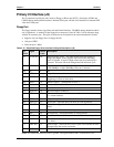
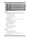
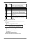
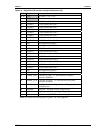
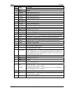
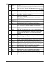
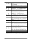
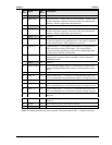
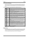
Pin # Signal Description
26 LCDD10 LVDS Channel Data Line 10
27, 28 GND Ground
29 LCDD04 LVDS Channel Data Line 4
30 LCDD07 LVDS Channel Data Line 7
31 LCDD05 LVDS Channel Data Line 5
32 LCDD06 LVDS Channel Data Line 6
33, 34 GND Ground
35 LCDD01 LVDS Channel Data Line 1
36 LCDD03 LVDS Channel Data Line 3
37 LCDD00 LVDS Channel Data Line 0
38 LCDD02 LVDS Channel Data Line 2
39, 40 VCC DC Power – +5V +/- 5%
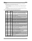
41 FPDDC_DAT Flat Panel I
2
C Data – I
2
C data interface to flat panel parameter EEPROM.
42 NC Not connected (LTGIO)
43 FPDDC_CLK Flat Panel I
2
C Clock – I
2
C clock interface to flat panel parameter EEPROM.
44 BLON* Backlight On – Control signal for external flat panel backlight power.
45 NC Not connected (BIASON)
46 DIGON Digital Power On – This signal controls the digital flat panel power up.
47 COMP Composite Analog Output
48 Y TV Luminance for S-Video
49 NC Not Connected (Composite Sync )
50 C TV Chrominance for S-Video
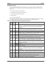
51 LPT/FLPY*
Parallel/Floppy Select – This input signal selects the parallel or floppy port
signal. If this signal is Low at boot time, the floppy drive is selected. If this
signal is High at boot time, the parallel port is selected. This state can not be
changed until the next boot cycle.
52 NC Not Connected (Reserved)
53 VCC DC Power – +5V +/- 5%
54 GND Ground
55 Strobe*
Parallel Strobe* – This output signal is used to strobe data into the printer.
I/O pin in ECP/EPP mode.
56 AFD*
DENSEL
Parallel Auto Feed * – This is a output signal from the printer to automatically
feed one line after each line is printed.
Floppy Drive Density Select – This signal indicates if a low (250/300kBps) or
high (500/1kBps) data rate is selected.
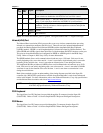
57 NC Not Connected (Reserved)
58 PD7 Parallel Port Data 7 – This signal (0 to 7) provides a parallel port data signal
and is the printer data MSB.
59 IRRX IR Receive Data (HPSIR or ASKIR)