


Chapter 3 Hardware
36 Reference Manual XTX 820
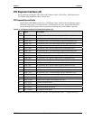
Parallel Port
Parallel port supports standard parallel, Bi-directional, ECP and EPP protocols. The Super I/O
(W83627HG) chip provides the parallel port interface signals.
• The Parallel interface shares signal lines with the Floppy interface. The BIOS settings determine
which one is operational.
• Supports Standard Printer Port (SPP), Enhanced Parallel Port (EPP) and Enhanced Capabilities
Port (ECP)
A Standard Parallel port cable pin-out is listed in Table 3-17 for reference along with the J3 connector
pins. A DB25 connector can be located on the custom baseboard if desired.
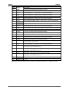
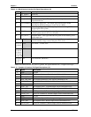
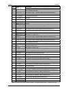
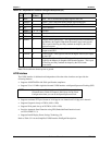
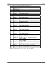
Table 3-17. Simplified Parallel Interface (SPP) Pin/Signal Descriptions (J3)
J3
Pin #
Signal DB25
Pin #
Description
51 LPT/FLPY* NC Parallel/Floppy Select – This input signal selects the parallel or
floppy port signal. If this signal is Low at boot time, the floppy
drive is selected. If signal is High at boot time, the parallel port is
selected. This state can not be changed until the next boot cycle.
55 Strobe* 1 Strobe* – This output signal is used to strobe data into the printer.
I/O pin in ECP/EPP mode.
80 PD0 2 Parallel Port Data 0 – This signal (0 to 7) provides a parallel port
data signal and is the LSB of printer data.
78 PD1 3 Parallel Port Data 1 – Refer to pin-2 and 9 for more information.
76 PD2 4 Parallel Port Data 2 – Refer to pin-2 and 9for more information.
74 PD3 5 Parallel Port Data 3 – Refer to pin-2 and 9for more information.
72 PD4 6 Parallel Port Data 4 – Refer to pin-2 and 9for more information.
68 PD5 7 Parallel Port Data 5 – Refer to pin-2 and 9for more information.
62 PD6 8 Parallel Port Data 6 – Refer to pin-2 and 9for more information.
58 PD7 9 Parallel Port Data 7 – This signal provides a parallel port data signal
and is the MSB of printer data.
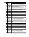
84 ACK* 10
Acknowledge * – This is a status input signal from the printer. A Low
State indicates it has received the data and is ready to accept new data.
86 BUSY 11 Busy – This is a status input signal from the printer. A high state
indicates the printer is not ready to accept data.
88 PE 12 Paper End – This is a status input signal from the printer. A high
state indicates it is out of paper.
90 SLCT 13
Select – This is a status output signal from the printer. A high state
indicates it is selected and powered on.
56 AFD* 14 Auto Feed * – This is a output signal from the printer to
automatically feed one line after each line is printed.
60 ERR* 15 Error – This is a status output signal from the printer. A low state
indicates an error condition on the printer.
64 INIT*
16
Initialize * – This signal initializes the printer. Output in standard
mode, I/O in ECP/EPP mode.
70 SLCTIN 17 Select In – This output signal is used to select the printer. I/O pin in
ECP/EPP mode.
66 GND 18-25 Ground
Notes: The shaded area denotes power or ground. The signals marked with * indicate active low.