Chapter 3 Hardware
XTX 820 Reference Manual 49
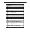
Power Control Signals
The XTX 820 supports various power control signals provided by the baseboard to control the XTX
module. These signals are listed here and in Tables 3-26 and 3-23.
• The Power Good input signal (PWGIN) is provided from an external input typically from the
external power supply (ATX) to the baseboard. This signal is typically an active-high input to
the XTX board and indicates to the XTX board it can begin the boot process. This Power Good
signal can also be used as an active-low reset input to the XTX module.
• The Power Suspend signal (5V_SB) must be provided by a power supply capable of standby
operation, typically an ATX power supply. The power supply must provide a 5 volt 100 ma
stand-by power source for this function to be available.
• The Power On signal (PS_ON) is provided by the XTX module to the PS_ON input of an ATX
power supply allowing it to switch to the main output power from a standby state. This signal is
used in conjunction with the 5V_SB supplied to the XTX module from the ATX power supply.
• The Power Button Input signal (PWRBTN*) provides a ground temporarily through a
momentary-contact switch or through an open collector driver to the ATX power supply. This
signal is used in conjunction with the PS_ON and the 5V_SB signals from the ATX power supply
to activate the power control button function of the power supply.
• A voltage monitor on the XTX 820 tracks the VCC voltage (+5 volts) state by monitoring the
+3.3V generated on the XTX module. When the +3.3V drops below 3.0V or the Reset Button
signal goes low, the voltage monitor sends a reset pulse to the Memory & Graphics Hub
(Northbridge) chip (82915GM), the I/O Hub (Southbridge) chip (82801FBM), Super I/O
(W83627HG) chip and the CPU.
Power Management Signals
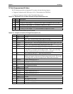
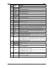
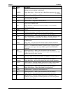
The XTX 820 supports various power management signals listed below and in Tables 3-20 and 3-22.
• The External System Management Interrupt (EXTSMI) signal is routed to the baseboard through
J4 to allow external circuitry to initiate an SMI for the EXT module.
• The Resume Reset input (RSMRST*) signal to the EXT module may be driven low by external
control circuitry to reset the power management logic on the XTX module.
• The System Management Bus Alert input (SMBALRT*) signal is used by SMBus devices to
indicate an event on the SMBus to the EXT module.
• The Battery Low input (BATLOW*) signal is used by external voltage monitoring circuitry to
indicate to the XTX module that the system battery is low.
NOTE Refer also to the additional Power Management Signals on J2.
Speaker
The signal lines for a speaker port with 0.1-watt drive are provided through J4 connector to the
baseboard where the speaker may be located.
• The Super I/O (83627HG) provides the speaker output signal, but the output driver circuit must
be implemented on the baseboard


