


Chapter 3 Hardware
XTX 820 Reference Manual 31
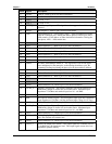
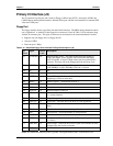
AC'97/HDA CODEC
The additional signals provided by J2 support AC'97 digital audio CODECs as well HDA (High
Definition Audio) audio CODECs.
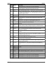
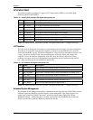
Table 3-12. Audio CODEC Interface Pin/Signal Descriptions (J2)
Pin # Signal Description
81 AC_RST* AC'97/HDA CODEC Reset
85 AC_SYNC AC'97/HDA Serial Bus Synchronization
89 AC_BIT_CLK AC'97/HDA 12.228 MHz Serial Bit Clock from CODEC
82 AC_SDOUT AC'97/HDA Audio Serial Data Output to CODEC
86 AC_SDIN0 AC'97/HDA Audio Serial Data Input from CODEC0
87 AC_SDIN1 AC'97/HDA Audio Serial Data Input from CODEC1
88 AC_SDIN2 AC'97/HDA Audio Serial Data Input from CODEC2
79 CODECSET AC`97/HDA Disable onboard Audio CODEC
Notes: The shaded area denotes power or ground. The signals marked with * = Negative true logic.
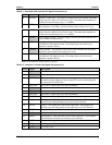
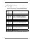
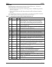
LPC Interface
The LPC (Low Pin Count) bus is provided as a replacement for the increasingly less often used ISA bus.
The LPC bus is used on PC-style personal computers to connect low-bandwidth devices to the CPU,
such as the boot ROM, "legacy" I/O devices (supported by a Super I/O chip), and audio controllers. The
"legacy" I/O devices usually include serial and parallel ports, keyboard, mouse, and a floppy disk
controller. Due to the software compatibility of the LPC bus to the ISA bus, I/O devices such as
additional serial ports can be easily implemented on an application specific baseboard using the LPC
bus. There are also many devices available for the LPC bus.
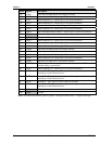
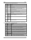
Table 3-13. LPC Interface Pin/Signal Descriptions (J2)
Pin # Signal Description
91 LPC_AD0 LPC Multiplexed Command, Address and Data Line 0
93 LPC_AD1 LPC Multiplexed Command, Address and Data Line 1
94 LPC_FRAME* LPC Frame – Indicates start of a new or termination of a broken cycle.
95 LPC_AD2 LPC Multiplexed Command, Address and Data Line 2
96 LPC_DRQ0* LPC Encoded DMA/Bus Master Request Line 0
97 LPC_AD3 LPC Multiplexed Command, Address and Data Line 3
98 LPC_DRQ1* LPC Encoded DMA/Bus Master Request Line 1
Notes: The shaded area denotes power or ground. The signals marked with * = Negative true logic.
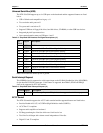
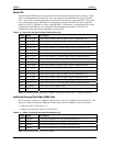
Extended System Management
The Extended System Management interface, implemented by the Super I/O chip (W83627HG), provide
additional signals and functions to further improve system management. One of these signals is an
output signal called FAN_PMOUT that allows system fan control using a PWM (Pulse Width
Modulation) Output. Additionally there is an input signal called FAN_TACHOIN that provides the
ability to monitor the system fan's RPMs (revolutions per minute).