


Chapter 3 Hardware
XTX 820 Reference Manual 41
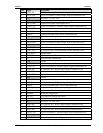
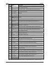
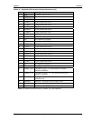
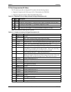
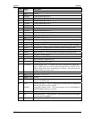
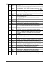
Table 3-21. Simplified LVDS Interface Pin/Signal Descriptions (J3)
J3 Pin # Signal Description
39, 40 VCC DC Power – +5V +/- 5%
GND Ground
37 LCDD00 LVDS Channel Data Line 0
35 LCDD01 LVDS Channel Data Line 1
38 LCDD02 LVDS Channel Data Line 2
36 LCDD03 LVDS Channel Data Line 3
29 LCDD04 LVDS Channel Data Line 4
31 LCDD05 LVDS Channel Data Line 5
32 LCDD06 LVDS Channel Data Line 6
30 LCDD07 LVDS Channel Data Line 7
23 NS Not Supported (LCDD08)
25 NS Not Supported (LCDD09)
26 LCDD10 LVDS Channel Data Line 10
24 LCDD11 LVDS Channel Data Line 11
19 LCDD12 LVDS Channel Data Line 12
17 LCDD13 LVDS Channel Data Line 13
20 LCDD14 LVDS Channel Data Line 14
18 LCDD15 LVDS Channel Data Line 15
11 LCDD16 LVDS Channel Data Line 16
13 LCDD17 LVDS Channel Data Line 17
12 NS Not Supported (LCDD18)
14 NS Not Supported (LCDD19)
41 FPDDC_DAT Flat Panel I
2
C Data – I
2
C data interface to flat panel
parameter EEPROM.
43 FPDDC_CLK Flat Panel I
2
C Clock – I
2
C clock interface to flat panel
parameter EEPROM.
44 BLON*
Backlight On – Control signal for external flat panel
backlight power.
45 BIASON BIAS ON – Flat panel contrast voltage control.
46 DIGON Digital Power On – Controls digital flat panel power on.
9 NC Not Connected (DETECT* = Panel hot-plug detection)
Notes: The shaded area denotes power or ground. NS = Not supported