


Chapter 3 Hardware
XTX 820 Reference Manual 19
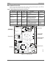
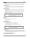
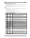
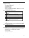
PCI Bus Interface Connector (J1)
The J1 connector has 100 pins and is used for the PCI bus, USB ports, IRQ lines, and Audio (AC’97)
interface connections.
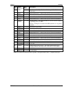
Tables 3-4 to 3-7 provide the signals and descriptions in a simplified form and Table 3-8 provides the
complete pin-outs for the X1 connector.
PCI Bus
The Memory & Graphics Hub (Northbridge) chip (82915GM) integrates a PCI arbiter that supports up to
four external PCI masters.
• This interface carries all of the appropriate PCI signals
• Operates at clock speeds up to 33 MHz.
• PCI 2.1 Compliant, 32-bit 3.3V PCI interface with 5V tolerant inputs
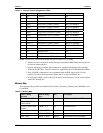
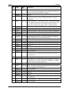
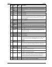
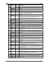
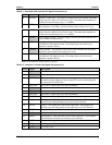
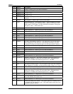
Table 3-4. Simplified PCI Pin/Signal Descriptions (J1)
J1
Pin #
Signal PCI
Pin #
Description
NC TRST* 1 (A1)
Test Reset – This signal provides an asynchronous initialization of
the TAP controller. One of five pins used for the optional
JTAG/Boundary Scan and TAP function.
NC +12V 2 (A2) +12 Volt Power
NC TMS 3 (A3) Test Mode Select – This signal is used to control the state of the
TAP controller in the device. One of five pins used for the optional
JTAG/Boundary Scan and TAP function.
NC TDI 4 (A4) Test Data Input is used to serially shift test data and test instructions
into the device during TAP operation. One of five pins used for the
optional JTAG/Boundary Scan and TAP function.
NC +5V 5 (A5) +5 Volt Power
97 INTA* 6 (A6) Interrupt A – This signal is used to request an interrupt.
95 INTC* 7 (A7) Interrupt C – This signal is used to request an interrupt.
NC +5V 8 (A8) +5 Volt Power
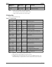
Reserved 9 (A9) Reserved
+3.3V I/O 10 (A10) +3.3V I/O
Reserved 11 (A11) Reserved
NC Key (3.3V) 12 (A12) +3.3V Key
NC Key (3.3V) 13 (A13) +3.3V Key
3.3Vaux 14 (A14)
3.3 Volt Auxiliary – This voltage is an optional power source that
delivers power to the PCI add-in card for generation of power
management events when the main power to the card has been turned
off by software. A system or add-in card that does not support PCI
bus power management must treat the 3.3Vaux pin as reserved.
93 PCIRST* 15 (A15) (PCI Bus) Reset – This signal is used to bring PCI-specific registers,
sequencers, and signals to a consistent state. Anytime Reset is
asserted, all PCI output signals must be driven to the benign state.
+3.3V(I/O) 16 (A16) +3.3V I/O