


Chapter 3 Hardware
56 Reference Manual XTX 820
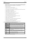
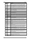
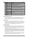
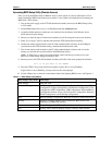
Pin # Signal Description
31 GND Ground
32 SDVO_FLDSTALL* Serial Digital Video field stall complement.
33 SDVO_FLDSTALL Serial Digital Video field stall.
34 GND Ground
35 SDVO_TVCLKIN* Serial Digital Video TV-Out synchronization clock complement.
36 SDVO_TVCLKIN Serial Digital Video TV-Out synchronization clock.
37 GND Ground
38 SDVOCTRL_CLK I²C based control signal (Clock) for SDVO device. PU 2k2 3.3V
39 SDVOCTRL_DATA I²C based control signal (Data) for SDVO device. PU 2k2 3.3V
40 PWRGD Power Good tied to Pull Up 10k resistor at 3.3V
41 +5V Power supply +5V
42 +5V Power supply +5V
43 +5V Power supply +5V
44 SDAOUFP1 Custom
45 SDAOUFP2 Custom
Notes: The shaded area denotes power or ground. The signals marked with * = Negative true logic.
Serial Console (Remote Access)
The XTX 820 supports the serial console (or console redirection) feature as Remote Access in the BIOS
Setup Utility. This I/O function can be accessed by an ANSI-compatible serial terminal, or the
equivalent terminal emulation software running on another system. This can be very useful when setting
up the BIOS on a production line for systems that are not connected to a keyboard and display.
Serial Console Setup
The serial console feature is implemented by connecting a standard null modem cable between one of
the serial ports, such as Serial 1 (COM1) or Serial 2 (COM2), and the serial terminal or a PC with
communications software. The BIOS Setup Utility controls the serial console settings for the XTX 820.
Refer to Chapter 4, BIOS Setup Utility for the Remote Access (serial console) settings, and the settings
for the serial terminal, or PC with communications software. A brief connection procedure is also
provided in Chapter 4, under Accessing BIOS Setup Utility (Remote Access).
Temperature Monitoring
Pentium/Celeron M processors make use of the thermal monitor feature to help control the processor
temperature. The maximum junction operating temperature for Pentium/Celeron M processors is 100°C.
The integrated TCC (Thermal Control Circuit) activates if the processor die reaches its maximum
operating temperature. The activation temperature used by the Intel Thermal Monitor activates the TCC,
but cannot be configured by the user nor is it software visible.
The Thermal Monitor can control the processor temperature through the use of two different methods
defined as TM1 and TM2. The TM1 method modulates (starts and stops) the processor clock at a 50%
duty cycle. The TM2 method initiates an Enhanced Intel Speedstep transition to the lowest performance
state once the processor silicon reaches the maximum operating temperature and is only supported by
Intel Pentium M processors. The TM2 mode should only be used for Intel Pentium M processors and is
not supported by Intel Celeron M processors.
The Thermal Monitor supports two modes (Automatic and On-Demand) to activate the TCC. The Intel
Thermal Monitor Automatic Mode must be enabled through a setup node in the BIOS. No additional
hardware, software, or handling routines are necessary when using Automatic Mode.