


Chapter 3 Hardware
XTX 820 Reference Manual 37
Serial Ports 1 and 2
The Super I/O (W83627HG) provides the circuitry for two serial ports with TTL compatible. Serial
ports 1 (COM1) and 2 (COM2) are provided to the baseboard through connector J3. The serial port
features are:
• Two individual 16550-compatible UARTs
• Programmable word length, stop bits and parity
• 16-bit programmable baud rate generator
• Loop-back mode
• Two individual 16-bit FIFOs
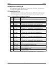
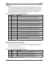
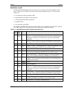
The standard serial DB9 cable pin-outs are listed in Table 3-18 for reference along with the J3 connector
pins. DB9 connectors can be located on the custom baseboard, as application requires.
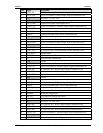
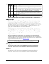
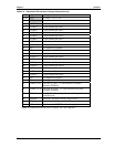
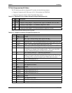
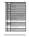
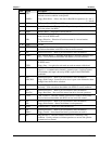
Table 3-18. Simplified Serial Interface Pin/Signal Descriptions (J3)
J3
Pin #
Pin #
DB9
Signal Description
89 1
(COM1)
DCD1* Data Carrier Detect 1 – Indicates external serial device is detecting a carrier
signal (i.e., a communication channel is currently open). In direct connect
environments, this input is driven by DTR1 as part of the DTR1/DSR1
handshake.
91 6 DSR1* Data Set Ready 1 – Indicates external serial device is powered, initialized,
and ready. Used as hardware handshake with DTR1 for overall readiness.
83 2 RXD1 Receive Data 1 – Serial port 1 receive data in.
85 7 RTS1* Request To Send 1 – Indicates Serial port 1 is ready to transmit data. Used
as hardware handshake with CTS1 for low level flow control.
95 3 TXD1 Transmit Data 1 – Serial port 1 transmit data out
93 8 CTS1* Clear To Send 1 – Indicates external serial device is ready to receive data.
Used as hardware handshake with RTS1 for low level flow control.
87 4 DTR1* Data Terminal Ready 1 – Indicates Serial port 1 is powered, initialized, and
ready. Used as hardware handshake with DSR1 for overall readiness.
97 9 RI1* Ring Indicator 1 – Indicates external serial device is detecting a ring
condition. Used by software to initiate operations to answer and open the
communications channel.
5 GND Ground
10 NC KEY/NC Key/Not connected
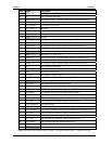
71
1
(COM2)
DCD2*
Data Carrier Detect 2 – Indicates external serial device is detecting a carrier
signal (i.e., a communication channel is currently open). In direct connect
environments, this input is driven by DTR2 as part of the DTR2/DSR2
handshake.
73 6 DSR2* Data Set Ready 2 – Indicates external serial device is powered, initialized,
and ready. Used as hardware handshake with DTR2 for overall readiness.
63 2 RXD2 Receive Data 2 – Serial port 2 receive data in
67 7 RTS2* Request To Send 2 – Indicates Serial port 2 is ready to transmit data. Used
as hardware handshake with CTS2 for low level flow control.
77 3 TXD2 Transmit Data 2 – Serial port 2 transmit data out