


Chapter 3 Hardware
50 Reference Manual XTX 820
Real Time Clock (RTC)/Battery
The XTX 820 supports a Real Time Clock (RTC) and CMOS RAM for the BIOS Setup Utility. The
RTC and 256 byte of CMOS RAM are included inside the I/O Hub (Southbridge) chip (82801FBM).
The RTC and CMOS are powered through pin-8 (BAT) on J4 with a Lithium Battery located on the
baseboard. If the battery is not present, the BIOS has a battery-free boot option to complete the boot
process. .
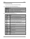
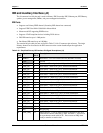
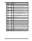
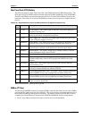
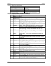
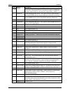
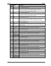
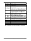
Table 3-26. Simplified Power Control and Miscellaneous Pin/Signal Descriptions (J4)
J4
Pin #
Signal Description
35V_SB
5 volt Suspend – This control signal is sent to the ATX power supply for a
suspend or standby state.
4PWGIN
Power Good In – This active high input signal indicates to the XTX 820, the
power is good and it can begin the boot process.
5 PS_ON Power Supply On – This active-low output signal from the XTX 820 is sent
to the ATX power supply to turn it on.
7 PWRBTN* Power Button – This signal provides a ground temporarily through an open
collector driver to the ATX power supply to change states (turn it on).
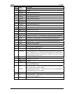
6 SPEAKER
Speaker – This PC speaker output signal must be connected to a speaker
(piezoelectric or dynamic) on the baseboard to hear the output (beeps).
11 RSMRST* Resume Reset – This signal is driven low by external circuitry to reset the
power management logic on the XTX 820.
19 OVCR Over Current Detect – This signal indicates a USB over-current condition.
8 BAT Battery Voltage – This is the + battery connection to baseboard for +3 volt
lithium backup battery used for RTC operation and CMOS non-volatile
memory.
41 BATLOW* Battery Low – This external signal to the XTX 820 indicates when the
external battery is low.
21 EXTSMI* Extern System Management Interrupt – This signal is provided by external
circuitry to initiate an SMI event with the XTX 820.
23 SMBCLK
System Management Bus Clock – This signal is used to support internal and
external SMBus devices, such as temperature and battery monitoring.
24 SMBDATA
System Management Bus Data – This signal is used to support internal and
external SMBus devices, such as temperature and battery monitoring.
26 SMBALRT* System Management Bus Alert – This signal is used by SMBus devices to
signal an event on the SM Bus.
Note: The shaded area denotes power or ground.
SMBus (I
2
C Bus)
The I/O Hub (82801FBM) contains an integrated SMBus controller with both a host and slave SMBus
port; but the host cannot access the slave internally. The slave port allows an external master access to
the I/O Hub (Southbridge) through the J4 connector. The master contained in the I/O Hub is used to
communicate with the Memory & Graphics Hub, DDR2 RAM EPROM, and the clock generator.
• The I
2
C slave address must not be the same as the I
2
C device on the baseboard.