


Chapter 3 Hardware
46 Reference Manual XTX 820
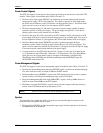
IDE and Auxiliary Interface (J4)
The J4 connector has 100 pins and is used for Primary IDE, Secondary IDE, Ethernet port, RTC/Battery,
speaker, power management, SMBus, and power management interfaces.
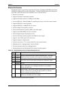
IDE Ports
• Supports one Primary EIDE channel (Secondary IDE channel not connected)
• Supports EIDE Ultra DMA 33/66/100 in Master Mode
• Master mode PCI supporting EIDE devices
• Supports ATAPI compliant devices including DVD devices
• PIO IDE transfers up to 14 Mbytes/sec
• Bus Master IDE transfers up to 100 Mbps
The standard 40-pin cable pin-outs are listed in Table 3-24 for J3 connector pin reference. The single
Primary channel can be routed to the IDE connector on the custom baseboard per the application
requirements.
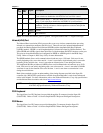
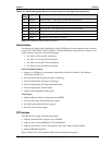
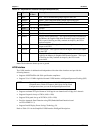
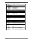
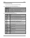
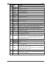
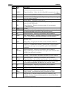
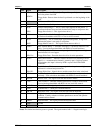
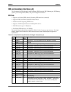
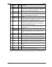
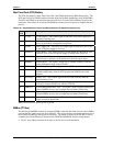
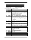
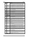
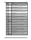
Table 3-24. Simplified Primary IDE Interface Pin/Signal Descriptions (J4)
J4
Pin #
Signal 40-
Pin #
Description
98 HDRST* 1 Hard Reset – Low active hardware reset (RSTDRV inverted)
GND 2 Ground
96 PIDE_D7 3 Disk Data – These signals (0 to 15) provide the disk data signals
92 PIDE_D8 4 Disk Data 8 – Refer to D7, pin-3, for more information.
88 PIDE_D6 5 Disk Data 6 – Refer to D7, pin-3, for more information.
86 PIDE_D9 6 Disk Data 9 – Refer to D7, pin-3, for more information.
84 PIDE_D5 7 Disk Data 5 – Refer to D7, pin-3, for more information.
80 PIDE_D10 8 Disk Data 10 – Refer to D7, pin-3, for more information.
78 PIDE_D4 9 Disk Data 4 – Refer to D7, pin-3, for more information.
76 PIDE_D11 10 Disk Data 11 – Refer to D7, pin-3, for more information.
74 PIDE_D3 11 Disk Data 3 – Refer to D7, pin-3, for more information.
72 PIDE_D12 12 Disk Data 12 – Refer to D7, pin-3, for more information.
70 PIDE_D2 13 Disk Data 2 – Refer to D7, pin-3, for more information.
68 PIDE_D13 14 Disk Data 13 – Refer to D7, pin-3, for more information.
64 PIDE_D1 15 Disk Data 1 – Refer to D7, pin-3, for more information.
62 PIDE_D14 16 Disk Data 14 – Refer to D7, pin-3, for more information.
60 PIDE_D0 17 Disk Data 0 – Refer to D7, pin-3, for more information.
58 PIDE_D15 18 Disk Data 15 – Refer to D7, pin-3, for more information.
GND 19 Ground
NC Key 20 Key pin plug
56 PIDE_DRQ 21
DMA Request – Used for DMA transfers between host and drive
(direction of transfer controlled by IOR* and IOW*). Also used in
an asynchronous mode with ACK*. Drive asserts an IRQ when
ready to transfer or receive data.