


Chapter 4 BIOS Setup Utility
68 Reference Manual XTX 820
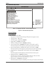
>PCI Express Configuration
♦ Active State Power-Management – [Disabled] or [Enabled]
This field enables or disables PCI Express L0 and L1 link power states.
• PCI Express Port 1 – [Disabled] or [Enabled]
• PCI Express Port 2 – [Disabled] or [Enabled]
• PCI Express Port 3 – [Disabled] or [Enabled]
• PCI Express Port 4 – [Disabled] or [Enabled]
• VC1 for Azalia & Root Ports – [Disabled] or [Enabled]
This field Enables or Disables Virtual Channel 1 for PCI Express Root Ports and the
Azalia controller (Intel High Definition Audio) to support true isochronous data transfers.
>I/O Interface Configuration
• Onboard Audio Controller – [Azalia], [AC97], or [Disabled]
∗ If this field is set to [AC97], the onboard AC'97 CODEC is selected.
∗ If this field is set to [Azalia], the onboard Intel High Definition Audio controller is selected.
• Onboard Ethernet Controller – [Disabled] or [Enabled]
This field must be set to [Enabled] to use the LAN Boot feature (PXE Boot to LAN).
• Onboard Floppy Controller – [Disabled] or [Enabled]
∗ If this field is [Enabled], the onboard floppy controller is selected over the Parallel Port and
the entry, 1
st
Floppy Drive, appears in the boot order under Boot Device Priority when Device
Type is selected. You must select a Floppy A type, typically [1.44 MB, 3 1/2"] to use this
feature. The Parallel Port can not be enabled since these two devices share the same pins to
the baseboard connector.
∗ If this field is [Disabled], the Parallel Port can be Enabled by selecting one of the Parallel port
address.
• Floppy A – [Disabled], [360 kB, 5 1/4 "], [1.2 MB, 5 1/4"], [720 kB, 3 1/2"], [1.44 MB, 3 1/2"], or
[2.88 MB, 3.5"]
• Serial Port 1 Configuration – [Disabled], [3F8/IRQ4], [3E8/IRQ4], or [2E8/IRQ3]
• Serial Port 2 Configuration – [Disabled], [2F8/IRQ3], [3E8/IRQ4], or [2E8/IRQ3]
♦ Serial Port 2 Mode – [Normal], [IrDA], or [ASK IR]
∗ If this field is set to [IrDA] or [ASK IR], the Infrared settings below appear on screen.
• IR Duplex mode – [Half Duplex] or [Full Duplex]
• IR I/O Pin select – [SINB/SOUTB] or [IRRX/IRTX]
• Parallel Port Address – [Disabled], [378], [278], or [3BC]
You can only change this feature from [Disabled] to another setting if the Onboard Floppy
Controller is set to [Disabled]. If [378], [278], or [3BC] are selected, the following items appear
on screen.
♦ Parallel Port Mode – [Normal], [Bi-Directional], [ECP], [EPP], or [ECP&EPP]
∗ If [Normal] is selected, the standard parallel port mode is used. This is the default setting.
∗ If [Bi-Directional] is selected, the data is sent to and received from the parallel port.
∗ If [ECP] is selected, the ECP Mode DMA Channel appears below. The ECP parallel port
can be used with devices adhering to the Extended Capabilities Port (ECP) specification.