


Chapter 3 Hardware
58 Reference Manual XTX 820
Power Input
The XTX 820 generates its own voltages on the board and only requires an external +5 volts through the
four connectors (X1, X2, X3, X4) on the custom baseboard. All the XTX 820 module voltages are
derived from the externally supplied +5 volts DC +/- 5%. The onboard voltages provide the CPU core
voltages as well as other voltages used on the module.
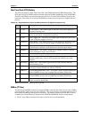
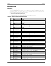
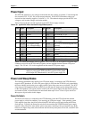
Table 3-30 gives the pin outs and signals for typical ATX Power supply connector.
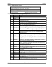
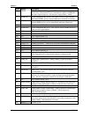
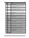
Table 3-30. Typical ATX Power Interface Pin/Signal Descriptions
Pin # Signal Description Pin
#
Signal Description
1 +3.3V +3.3 volts DC +/- 5% 2 +3.3V +3.3 volts DC +/- 5%
3 GND Ground 4 +5V +5.0 volts DC +/- 5%
5 GND Ground 6 +5V +5.0 volts DC +/- 5%
7 GND Ground 8 PWROK
Power Ok or Good signal from ATX
Power supply
9 5V_SB +5.0 suspend voltage
(+5V, 100mA Standby)
10 +12V This +12V is are for BUS power only
(optional)
11 +3.3V +3.3 volts DC +/- 5% 12 -12V This -12V is are for BUS power only
(optional)
13 GND Ground 14 PS_ON* Enable signal for ATX power supply
15 GND Ground 16 GND Ground
17 GND Ground 18 -5V -5.0 volts DC +/- 5%
19 +5V +5.0 volts DC +/- 5% 20 +5V +5.0 volts DC +/- 5%
Notes: The shaded area denotes power or ground. The +12V and +3.3V on a typical ATX power input
connector are used for the PCI bus and LCD panels, and are supplied from the external ATX power
supply. The -5V and –12V are also supplied from the external ATX power supply.
NOTE If you use a non-ATX type power supply (AT or lab power
supply) to power up the XTX baseboard, you must set the jumper
on the Ampro XTX Baseboard for a non-ATX power supply use.
Power and Sleep States
The following information only applies if an ATX power supply is connected to the XTX 820 and its
respective XTX baseboard. If a non-ATX power supply is used, then the XTX 820 is only controlled by
the Power-On/Off switch on the power supply and the various sleep states are not available. The ACPI
sleep states are OS dependent and not available if your OS does not support power management based
on the ACPI standard. The signals used for control of the ATX power supply and sleep states in general
are located in Table 3-30 and described in more detail under topics Power Control Signals and Power
Management Signals earlier in this chapter.
Power-On Switch
The Power-On switch on or connected to the XTX Baseboard, turns the XTX 820 and the attached
power supply to a fully On condition, if you are using an ATX power supply. If the operating system
(OS) supports sleep states, the OS will turn off the XTX 820 and its power supply during the OS shut
down process. Typically, the Power-On switch will also transition the XTX 820 and the power supply
between a fully powered on state and the various sleep states, including a fully powered off state. If the
OS does not support sleep states, then the Power-On switch only turns power, On or Off, to the XTX 820
and the baseboard.