


Chapter 3 Hardware
XTX 820 Reference Manual 35
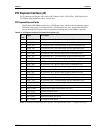
Primary I/O Interface (J3)
The J3 connector has 100 pins and is used for Floppy or Printer port (LPT1), Serial ports (COM1 and
COM2) Mouse and Keyboard interfaces, Infrared (IrDA) port, and the video interfaces for standard CRT
video and LVDS ports.
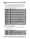
Floppy Port
The floppy interface shares signal lines with the Parallel interface. The BIOS settings determine which
one is operational. A standard 34-pin floppy drive connector is listed in Table 3-16 for reference along
with the J3 connector pins. This type of connector can be located on the custom baseboard if desired.
• Supports only one floppy drive on floppy drive B
• 16 bytes of FIFO
• Data rate up to 1 Mbps
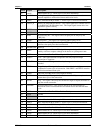
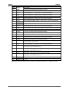
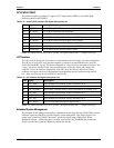
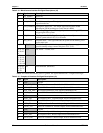
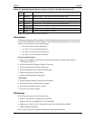
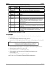
Table 3-16. Simplified Floppy Drive Interface Pin/Signal Descriptions (J3)
J3
Pin #
Signal
34-Pin
Cable
Description
51 LPT/FLPY* NC Parallel/Floppy Select – This input signal selects the parallel or
floppy port signal. If this signal is Low at boot time, the floppy
drive is selected. If signal is High at boot time, the parallel port is
selected. This state can not be changed until the next boot cycle.
56 DENSEL 2 Drive Density Select (Bit 0) – This signal indicates when a low
(250/300kBps) or high (500/1kBps) data rate is selected.
NC NC 4 NC
NC KEY 6 Key – Not connected
80 INDEX* 8 Index – This signal indicates when head is positioned over the
beginning of a track or index hole.
86 MOT1* 16 Motor Control 1 – Select motor on drive 1.
55 Reserved 14 Reserved (Drive Select 0)
84 DRV1* 12 Drive Select 1 – Select drive 1.
58 Reserved 10 Reserved (Motor Control 0)
64 DIR* 18 Direction – Direction of head movement (0 = inward motion,
1 = outward motion).
70 STEP* 20 Step – Low pulse for each track-to-track movement of the head.
88 WDATA* 22 Write Data – Encoded data to the drive for write operations.
90 WGATE* 24
Write Gate – Signal to the drive to enable current flow in the write
head.
78 TRK0* 26 Track 0 – Sense detects the head is positioned over track 0.
76 WP* 28 Write Protect – Senses the diskette is write protected.
74 RDATA* 30 Read Data – Raw serial bit stream from the drive for read operations.
60 HDSEL* 32
Head Select – Selects the side for Read/Write operations (0 = side 1,
1 = side 0)
72 DSKCHG* 34 Disk Change – Senses the drive door is open or the diskette has been
changed since the last drive selection.
66 GND all odd Ground (1-33)
Notes: The shaded area denotes power or ground. The signals marked with * indicate active low.