


Chapter 3 Hardware
XTX 820 Reference Manual 51
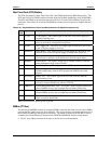
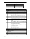
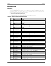
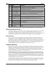
Table 3-27. SMBus Reserved Addresses
Matrix Component Address Binary
Memory & Graphics Hub (82915GM) 1010,010x
b
DDR2 RAM EPROM 1010,000x
b
Clock Generator (UICS954201) 1101,001x
b
I/O Hub (82801FBM) 0000,000x
b
(default) Programmable
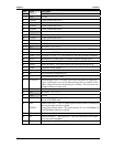
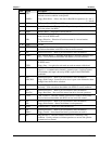
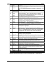
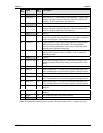
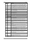
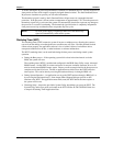
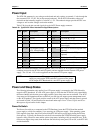
Table 3-28. Complete J4 Interface Pin/Signal Descriptions (J4)
Pin # Signal Description
1 GND1
Ground
2 GND3
Ground
35V_SB
5 volt Suspend – This control signal is sent to the ATX power supply for a
suspended or standby state.
4PWGIN
Power Good In – This active high input signal indicates to the XTX 820,
the power is good and it can begin the boot process.
5 PS_ON
Power Supply On – This active-low output signal from the XTX 820 is sent
to the ATX power supply from the to turn it on.
6 SPEAKER Speaker – This PC speaker output signal must be connected to a speaker
(piezoelectric or dynamic) on the baseboard to hear the output (beeps).
7 PWRBTN* Power Button – This signal provides a ground temporarily through an open
collector driver to the ATX power supply to change states (turn it on).
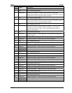
8BATT
Battery Voltage – This is the + battery connection to the baseboard for +3
volt lithium backup battery used to power RTC operation and CMOS
non-volatile memory.
9KBINH
Keyboard Inhibit – This pin disables data input from the keyboard when
asserted.
10 LILED Link Integrity LED – The LINK LED pin indicates link integrity. If the
link is valid in either 10 or 100 Mbps, the LED is on; if the link is invalid,
the LED is off.
11 RSMRST* Resume Reset – This signal is driven low by external circuitry to reset the
power management logic on the XTX 820.
12 ACTLED Activity LED – The Activity LED pin indicates either transmit or receive
activity. When activity is present, the activity LED is on; when no activity
is present, the activity LED is off.
13 NC Not Connected (ROMKBCS*)
14 SPDLED
Speed LED – The speed LED pin indicates the speed. The speed LED will
be on at 100 Mbps and off at 10 Mbps.
15 EXT_PRG External Programming – This pin is used when handling external flash
programming.
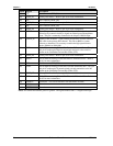
16 I
2
CLK I
2
C Clock – This clock line supports the I
2
C bus.
17 VCC1 +5 volts +/-5%
18 VCC3 +5 volts +/-5%
19 OVCR* Over Current Detect – This signal indicates a USB over-current condition.
20 NC Not Connected (GPCS*)
21 EXTSMI*
Extern System Management Interrupt – This signal is provided by external
circuitry to initiate an SMI event with the XTX 820.