


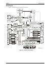

Chapter 3 Hardware
16 Reference Manual XTX 820
CPU (U1)
The XTX 820 offers three Intel processor choices; high performance 1.0 GHz Ultra Low Voltage
(ULV) Celeron M CPU, 1.4 GHz Low Voltage (LV) Pentium M CPU, or 1.8 GHz Pentium M CPU.
Celeron M Processor
The Celeron M processor (Dothan core) at 1.0 GHz has 512 kB L2 Cache with a 400 MHz FSB
(front side bus). The 1.0 GHz Celeron M 373 processor use 90 nm architecture and requires a
heatsink, but no fan.
Pentium M Processors
The Pentium M 738 processor (Dothan core) at 1.4 GHz has 2 MB L2 Cache with a 400 MHz FSB
(front side bus). The 1.4 GHz Pentium M 738 processor uses 90 nm architecture and requires a
heatsink, but no fan.
The Pentium M 745 processor (Dothan core) at 1.8 GHz has 2 MB L2 Cache with a 400 MHz FSB
(front side bus). The 1.8 GHz Pentium M 745 processor uses 90 nm architecture and requires a
heatsink, but no fan below 60°C.
CAUTION If you choose to use a heat-spreader plate instead of an individual
heatsink for the processor, then you must provide an additional form
of cooling. The heat-spreader plate is not a complete thermal
solution for any of the processors listed.
Memory
The XTX 820 memory consists of the following elements:
• DDR2 SODIMM socket
• Flash memory
DDR2 SODIMM Socket (J5)
The XTX 820 supports a single 200-pin DDR2 SODIMM socket.
• SODIMM socket (J5) can support up to 1 GB of DDR2 memory
• Supports PC2 3200 DDR 400 operating at 400 Mbps (200 MHz, 5 ns) or faster
• Supports +1.8V SDRAM
NOTE Ampro recommends using PC2 3200 DDR2 400 (400 Mbps, 200 MHz),
+1.8V, 5 ns, 200-pin, SDRAM SODIMM, or faster. PC2 3200 provides
the best performance for these Intel processors.
Flash Memory (U17)
There is an 8-bit wide, 512 kB flash device used for system BIOS and is connected to the I/O Hub
(Southbridge), through an LPC bus transceiver. The flash memory is used to store system parameters for
battery-free boot capability when there is no battery present. The BIOS is re-programmable and the
features supported are detailed in Chapter 4, BIOS Setup Utility.
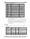
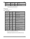
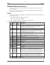
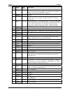
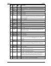
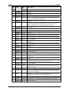
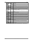
Interrupt Channel Assignments (IRQs)
The channel interrupt assignments are listed in Table 3-1.