


4. Connections
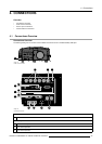
4.3.1 5–Cable Input
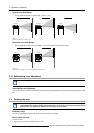
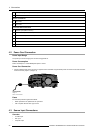
Which signals can be connected to the 5–Cable Input?
Input Signal / BNC
Connector
R
G
B H V
RGBHV
R
G
B H V
RGBS
R
G
B
S
–
RGsB
R
Gs
B
– –
Option
To display Component, the software option (ROPT202
3) has to be activated.
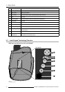
How to connect to the 5–Cable Input?
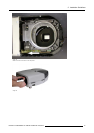
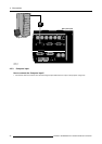
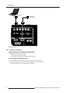
1. Connect the BNC’s from the source signal output cable to the 5–Cable Input on the projector. (image 4-4)
R / PR G / Y B / PB Hs / Cs Vs Optional
Optional
DVI
COMPUTER RS 232 C
RS232/422 OUTRS232/422 IN
IN L/R Signal10/100Base-T
Communication
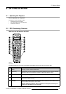
R.C.
OUT Phased L/R Signal
Image Generator
Sim 5 plus Inputs
Image 4-4
5–Cable Input
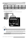
4.3.2 DVI Input
DVI
Digital Visual Interface is a display interface developed in response to the proliferation of digital flat panel displays.
The digital video connectivity standard that was developed by DDWG (Digital Display Work Group). This connection
standard offers two different connectors: one with 24 pins that handles digital video signals only, and one with 29 pins
that handles both digital and analog video. This standard uses TMDS (Transition Minimized Differential Signal) from
Silicon Image and DDC (Display Data Channel) from VESA (Video Electronics Standards Association).
DVI
canbesingleorduallink.
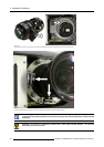
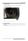
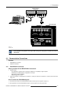
How to connect the DVI Input?
1. Con
nect the DVI connector from the source signal output cable to the DVI Input on the projector. (image 4-5)
R5976870 BARCOREALITY SIM 5PLUS/SIM 5R 04/04/2007
27