


Conettix D6600/D6100 | Computer Interface Manual | 2.0 Making the Right Connection
8 Bosch Security Systems, Inc. | 1/07 | 4998122703-01
2.0 Making the Right
Connection
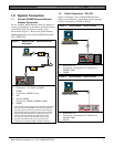
2.1 COM3 DB9 Connector
The COM3 Port uses a standard DB9 female
connector. The suggested connection to the computer
is shown in Figure 4 to Figure 6.
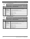
When connecting data terminal equipment (DTE)
together (such as a COM1 port to PC serial port), a
null-modem cable must be used. One possible
configuration for a null-modem cable is shown in
Figure 4.
Figure 4: Null Modem Cable Configuration
1
2
3
4
6
7
8
9
1
2
3
4
6
7
8
9
DTE
DB-9 Pin
DTE
DB-9 Pin
5 5
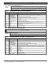
When connecting data terminal equipment to data
communication equipment (DCE) (such as the
D6600/D6100 COM port to a modem), a modem
cable should be used (such as a straight-through cable
shown in Figure 5).
Figure 5: Straight-through Modem Cable
Configuration
DTE
1
2
3
4
5
6
7
8
9
DCE
8
3
2
20
7
6
4
5
22
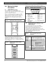
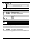
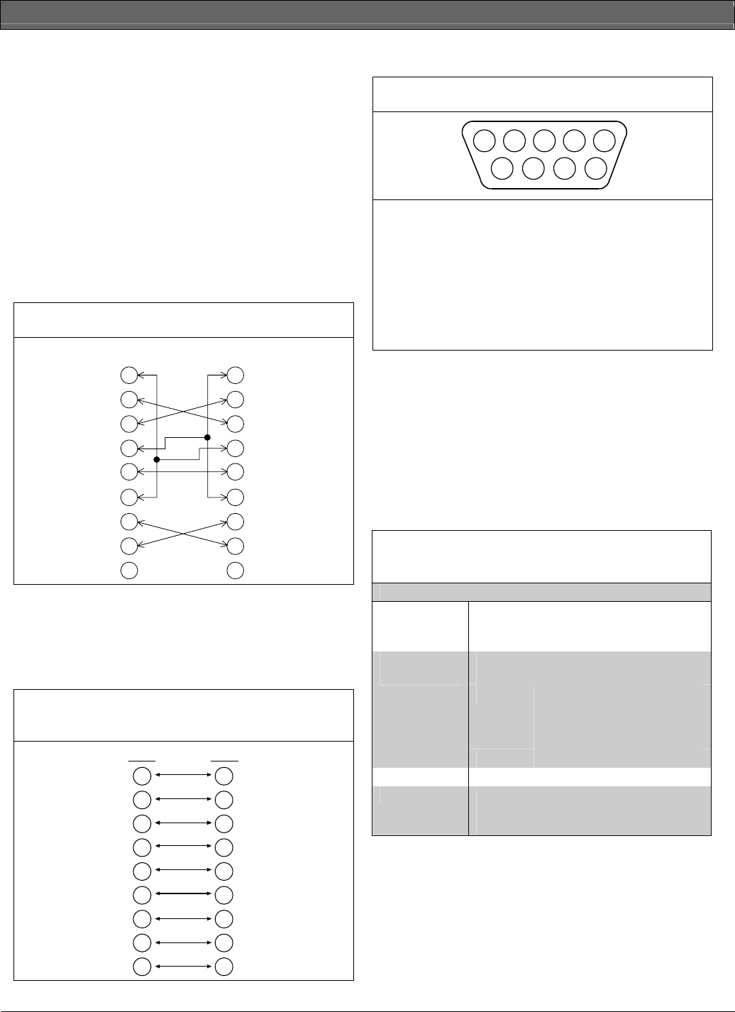
Each pin of the modem cable is defined in Figure 6.
Figure 6: Modem Cable Pin Definitions
1 2 3 4 5
6 7 8 9
1 - Data carrier detect
(DCD)
2 - Receive (RX)
3 - Transmit (TX)
4 - Data terminal ready
(DTR)
5 - Signal-ground
(SIG-GND)
6 - Data set ready
(DSR)
7 - Ready to send
(RTS)
8 - Clear to send
(CTS)
9 - Ring indicator (RI)
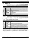
2.2 Selecting Program Options in the
D6600/D6100
Use the D6600/D6100 keypad or the D6200
Programming Software to program the receivers.
Below are the recommended selections for
programming when connecting the receivers to an
automation system. Additional selections can be found
in the D6600/D6100 Program Entry Guide
(P/N: 4998122702).
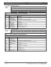
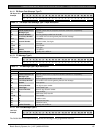
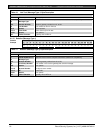
Table 1: Recommended Programming
Selections
Receiver
Gateway
Number
Selects a number (01 to 99) that is
included in every message to the
computer in both D6500 and SIA modes
Enable computer output messages in the
selected format:
SIA computer interface standard
format, recommended
(expanded reporting
capabilities)
Output
Format
D6500 21-character format output
Baud Rate
Use maximum speed supported by PC
Link Test
Tests if a supervision signal can be sent
and received from the central station by
the receiver