


4-91
FAX-L1000 Chapter 4: Maintenance and Service
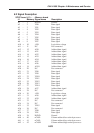
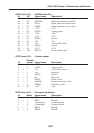
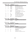
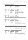
SCNT board (J25) ,/ NCU board (J6)
J25 J6 Signal name Description
1 . 14 OUT Direct current of line detection signal
2 / 13 IPSEL1 HIC terminal impedance setting
3 / 12 IPSEL2 HIC terminal impedance setting
4 . 11 IPSEL3 HIC terminal impedance setting
5 / 10 DCSEL DC registance switching when line is
connected
6 , 9 DCLIM DC current limitation control signal
7 , 8 RRD R relay control signal
8 , 7 NOR CI reception sensitivity setting signal when
no ringing reception
9 , 6 C1 DC cut capacitor selection signal
10 , 5 C2 DC cut capacitor selection signal
11 , 4 CIST1 CI reception sensitivity setting signal
12 , 3 CIST2 CI reception sensitivity setting signal
13 , 2 AST For Australian regulations signal
14 , 1 NZ For N.Z. regulations signal
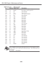
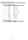
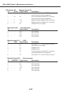
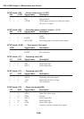
NCU board (J4) ,/ Power Supply unit (CN22)
J4 CN22 Signal name Description
1 , 2 VH For off-hook detection during communication
2 . 1 VH-GND Ground
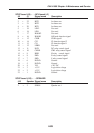
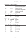
NCU board (J5) ,/ to Grounding wire
J5 G.wire Signal name Description
1 .. ARG Ground (arrester)
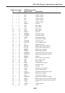
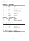
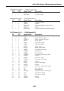
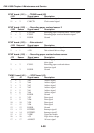
NCU board (J7) ,/ Modular board (J3)
J7 J3 Signal name Description
1 . 6 T2 Line from L1, L2 to wall socket via the fax
2 . 5 W Line from handset terminal T11 in priority
mode (handset/extension telephone).
3 . 4 L2 Telephone line
4 . 3 L1 Telephone line
5 . 2 R Outside line access signal
6 . 1 T1 Line from L1, L2 to wall socket via the fax