


5-74
FAX-L1000 Chapter 5: Appendix
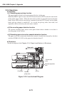
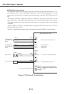
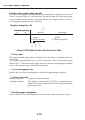
d) Electrical circuit section
The operation sequences of the paper feeder are controlled by the paper feeder driver. A 4-
bit microprocessor is used in the paper feeder driver, which controls the sequences of the
paper feeder and the serial communication with the engine controller (ECNT board) of this
fax.
The engine controller outputs the pick-up command to the paper feeder driver at the
necessary timing. The paper feeder driver drives the solenoid in response to the command.
The paper feeder driver also sends back the status of the paper feeder to the engine
controller.
This fax supplies +24VDC to the paper feeder. The paper feeder driver generates +3.3V for
the ICs based on this +24V.
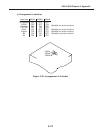
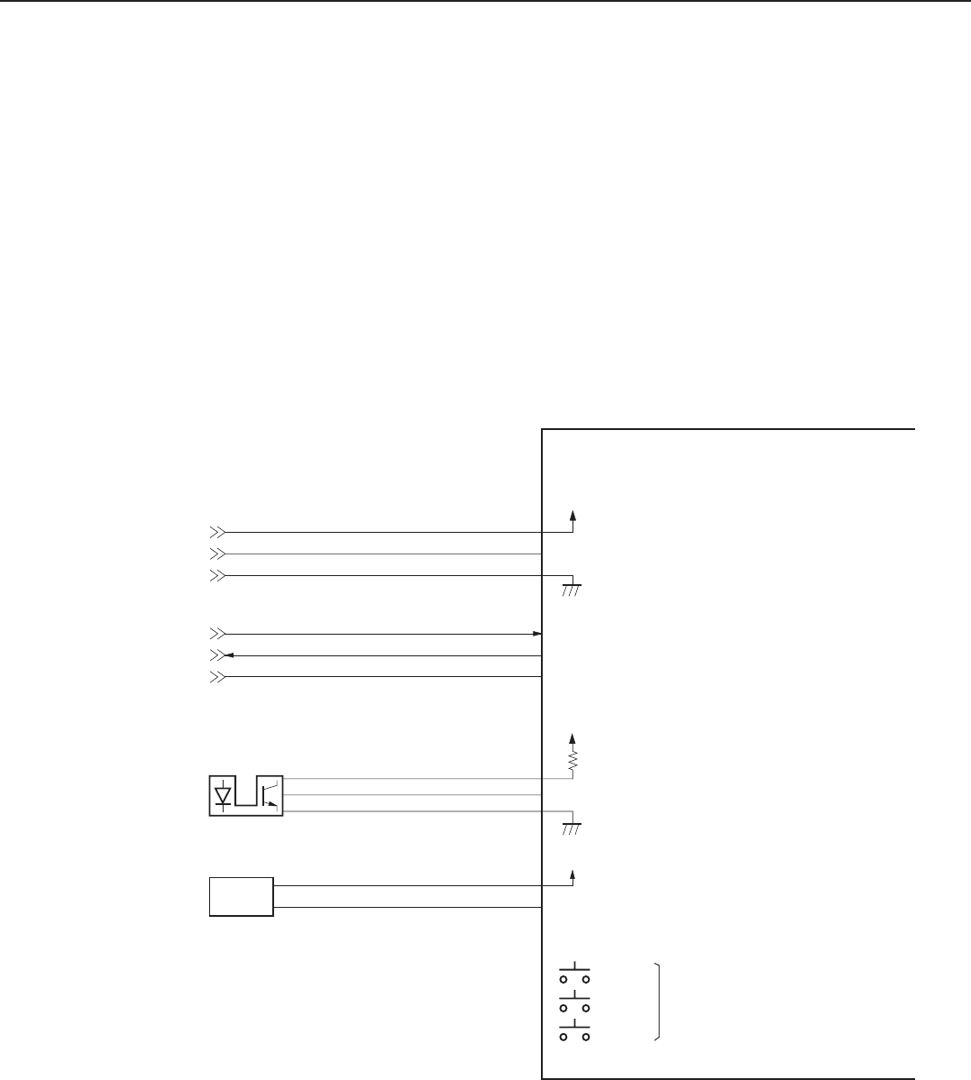
The flow of input/output signals to/from the paper feeder driver PCB is as shown below.
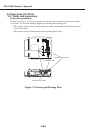
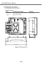
Figure 5-27 Electrical Circuit Section
Paper feeder driver PCB
Accepts the command when "L."
/SEL1
+24VA
J801-1
-2
-3
J811-3
-2
-1
To ECNT board
via PAPER SIZE
board
Command input
Status output
Serial clock
SOUT
SIN
SCLK
J801-4
-5
-6
J812-3
-2
-1
Paper sensor
PS801
J813-3
-1
-2
+24VA
J803-1
-3
-2
OPT SNS
"L" when the sensor detects paper.
+24VA
Pick-up solenoid
SL801
OPT SOL
Starts paper pick-up when "L."
Paper size detection switches
Size of the paper in the cassette is
detected by the combinations of these
switches.
SW801
SW802
SW803
J802-1
-2
To ECNT board
via PAPER SIZE
board