5-105
FAX-L1000 Chapter 5: Appendix
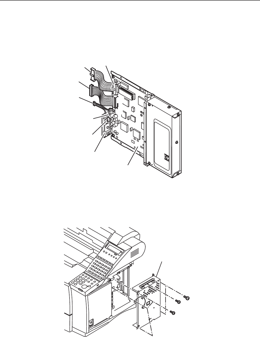
(6) Refer to Figure 5-43 and bend cables 1 and 2 as shown in order to make insertion of
the kit easier.
(7) Insert cables 1 and 2 into J2 and J1 on the G4 board ass’y.
(8) Insert the connectors of cable 3 into J1 and J2 on the G4 relay board unit. Then Insert
the other connector into J3 on the G4 board ass’y.
Figure 5-45 Preparation for Installation 2
If a FAX-L1000 Printer kit (Option) is installed proceed to step (10).
(9) Remove the six screws and remove the shield cover.
Figure 5-46 Preparation for Installation 3A
Cable 1
Cable 2
Cable 3
J2
J1
J2
G4 RELAY BOARD UNIT
G4 BOARD ASS'Y
J1
J3
Shield cover


