


53-7
Software Configuration Guide—Release 15.0(2)SG
OL-23818-01
Chapter 53 Onboard Failure Logging (OBFL)
Information About OBFL
Interrupts
Interrupts are generated by system components that require attention from the CPU such as ASICs and
NMIs. Interrupts are generally related to hardware limit conditions or errors that need to be corrected.
The continuous format records each time a component is interrupted, and this record is stored and used
as base information for subsequent records. Each time the list is saved, a timestamp is added. Time
differences from the previous interrupt are counted, so that technical personnel can gain a complete
record of the component’s operational history when an error occurs.
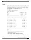
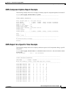
Interrupts Example
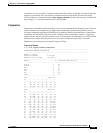
Switch# sh logging onboard interrupt detail
--------------------------------------------------------------------------------
INTERRUPT SUMMARY INFORMATION
--------------------------------------------------------------------------------
Name | ID | Offset | Bit | Count
--------------------------------------------------------------------------------
dropped 2 0x0004 0 27323
ipp 6 0x5A00 0 983763
ipp high 10 0x700A 0 34105
ipp low 11 0x9000 0 30211
--------------------------------------------------------------------------------
--------------------------------------------------------------------------------
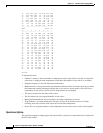
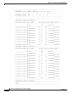
CONTINUOUS INTERRUPT INFORMATION
--------------------------------------------------------------------------------
MM/DD/YYYY HH:MM:SS mmm | Name | ID | Offset | Bit
--------------------------------------------------------------------------------
12/12/2011 16:06:43 0 ipp high 10 0x7AEA 7
12/12/2011 16:06:43 0 dropped 2 0x0006 0
12/12/2011 16:06:46 0 ipp high 10 0x7AEC 0
12/12/2011 16:06:46 0 ipp high 10 0x7AEC 1
12/12/2011 16:06:46 0 ipp high 10 0x7AEC 4
12/12/2011 16:06:46 0 ipp high 10 0x7AEC 5
12/12/2011 16:06:46 0 ipp low 11 0xC000 0
12/12/2011 16:06:46 0 ipp low 11 0xC000 1
12/12/2011 16:06:46 0 ipp low 11 0xC000 4
12/12/2011 16:06:46 0 ipp low 11 0xC000 5
12/12/2011 16:06:46 0 ipp high 10 0x7AEA 0
12/12/2011 16:06:46 0 ipp high 10 0x7AEA 2
12/12/2011 16:06:46 0 ipp high 10 0x7AEA 3
12/12/2011 16:06:46 0 ipp high 10 0x7AEA 4
12/12/2011 16:06:46 0 ipp high 10 0x7AEA 6
12/12/2011 16:06:46 0 ipp high 10 0x7AEA 7
12/12/2011 16:06:46 0 dropped 2 0x0006 0
12/12/2011 16:06:49 0 ipp high 10 0x7AEC 0
12/12/2011 16:06:49 0 ipp high 10 0x7AEC 1
--------------------------------------------------------------------------------
Switch#
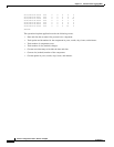
To interpret this data:
• Name is a description of the component including its position in the device.
• ID is an assigned field for data storage.
• Offset is the register offset from a component register’s base address.
• Bit is the interrupt bit number recorded from the component’s internal register.
• The timestamp shows the date and time that an interrupt occurred down to the millisecond.