


18-2
Software Configuration Guide—Release 15.0(2)SG
OL-23818-01
Chapter 18 Configuring STP and MST
About STP
A Catalyst 4500 series switch use STP (the IEEE 802.1D bridge protocol) on all VLANs. By default, a
single spanning tree runs on each configured VLAN (provided you do not manually disable the spanning
tree). You can enable and disable a spanning tree on a per-VLAN basis.
When you create fault-tolerant internetworks, you must have a loop-free path between all nodes in a
network. The spanning tree algorithm calculates the best loop-free path throughout a switched Layer 2
network. Switches send and receive spanning tree frames at regular intervals. The switches do not
forward these frames, but use the frames to construct a loop-free path.
Multiple active paths between end stations cause loops in the network. If a loop exists in the network,
end stations might receive duplicate messages and switches might learn end station MAC addresses on
multiple Layer 2 interfaces. These conditions result in an unstable network.
A spanning tree defines a tree with a root switch and a loop-free path from the root to all switches in the
Layer 2 network. A spanning tree forces redundant data paths into a standby (blocked) state. If a network
segment in the spanning tree fails and a redundant path exists, the spanning tree algorithm recalculates
the spanning tree topology and activates the standby path.
When two ports on a switch are part of a loop, the spanning tree port priority and port path cost setting
determine which port is put in the forwarding state and which port is put in the blocking state. The
spanning tree port priority value represents the location of an interface in the network topology and how
well located it is to pass traffic. The spanning tree port path cost value represents media speed.
These sections describe STP:
• Understanding the Bridge ID, page 18-2
• Bridge Protocol Data Units, page 18-3
• Election of the Root Bridge, page 18-4
• STP Timers, page 18-4
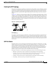
• Creating the STP Topology, page 18-5
• STP Port States, page 18-5
• MAC Address Allocation, page 18-6
• STP and IEEE 802.1Q Trunks, page 18-6
• Per-VLAN Rapid Spanning Tree, page 18-6
Understanding the Bridge ID
Each VLAN on each network device has a unique 64-bit bridge ID consisting of a bridge priority value,
an extended system ID, and an STP MAC address allocation.
Bridge Priority Value
The bridge priority value determines whether a given redundant link is given priority and considered part
of a given span in a spanning tree. Preference is given to lower values, and if you want to manually
configure a preference, assign a lower bridge priority value to a link than to its redundant possibility.
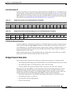
With Cisco IOS releases prior to 12.1(12c)EW, the bridge priority is a 16-bit value (see Table 18-1).With
Cisco IOS Release 12.1(12c)EW and later releases, the bridge priority is a 4-bit value when the extended
system ID is enabled (see Table 18-2). See the “Configuring the Bridge Priority of a VLAN” section on
page 18-17.