


25-13
Software Configuration Guide—Release 15.0(2)SG
OL-23818-01
Chapter 25 Configuring 802.1Q Tunneling, VLAN Mapping, and Layer 2 Protocol Tunneling
About Layer 2 Protocol Tunneling
Use the no switchport vlan mapping vlan-id dot1q-tunnel outer vlan-id command to remove the
VLAN mapping configuration. Entering the no switchport vlan mapping all command deletes all
mapping configurations.
This example shows how to configure selective QinQ mapping on the port so that traffic with a C-VLAN
ID of 1 to 5 enters the switch with an S-VLAN ID of 100. The traffic of any other VLAN IDs is dropped.
Switch(config)# interface gigabiethernet0/1
Switch(config-if)# switchport vlan mapping 1-5 dot1q-tunnel 100
Switch(config-if)# exit
About Layer 2 Protocol Tunneling
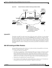
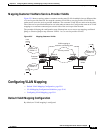
Customers at different sites connected across a service provider network need to use various Layer 2
protocols to scale their topologies to include all remote and local sites. STP must run properly, and every
VLAN should build a proper spanning tree that includes the local site and all remote sites across the
service provider network. Cisco Discovery Protocol (CDP) must discover neighboring Cisco devices
from local and remote sites. VLAN Trunking Protocol (VTP) must provide consistent VLAN
configuration throughout all sites in the customer network.
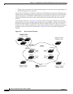
When protocol tunneling is enabled, edge switches on the inbound side of the service provider network
encapsulate Layer 2 protocol packets with a special MAC address and send them across the service
provider network. Core switches in the network do not process these packets but forward them as normal
packets. Layer 2 protocol data units (PDUs) for CDP, STP, or VTP cross the service provider network
and are delivered to customer switches on the outbound side of the service provider network. Identical
packets are received by all customer ports on the same VLANs with these results:
• Users on each of a customer’s sites can properly run STP, and every VLAN can build a correct
spanning tree, based on parameters from all sites and not just from the local site.
• CDP discovers and shows information about the other Cisco devices connected through the service
provider network.
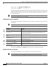
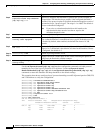
Command Purpose
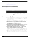
Step 1
Switch# configure terminal
Enters global configuration mode.
Step 2
Switch(config)# interface
interface-id
Enters interface configuration mode for the interface connected to the
service provider network. You can enter a physical interface or an
EtherChannel port channel.
Step 3
Switch(config-if)# switchport mode
trunk
Configure the interface as a trunk port.
Step 4
Switch(config-if)# switchport vlan
mapping vlan-id
dot1q-tunnel outer
vlan-id
Enters the VLAN IDs to be mapped:
• vlan-id—the customer VLAN ID (C-VLAN) entering the switch
from the customer network. The range is from 1 to 4094. You can
enter a string of VLAN-IDs.
• outer-vlan-id—Enter the outer VLAN ID (S-VLAN) of the service
provider network. The range is from 1 to 4094.
Step 5
Switch(config-if)# end
Returns to privileged EXEC mode.
Step 6
Switch# show interfaces
interface-id vlan mapping
Verifies the configuration.
Step 7
Switch# copy running-config
startup-config
(Optional) Saves your entries in the configuration file.