


10-9
Software Configuration Guide—Release 15.0(2)SG
OL-23818-01
Chapter 10 Environmental Monitoring and Power Management
Power Management
Your switch hardware configuration dictates which power supply or supplies you should use. For
example, if your switch configuration requires more power than a single power supply provides, use the
combined mode. In combined mode, however, the switch has no power redundancy. Consider the
following possibilities:
• The supervisor engine consumes 110 W, the fan boxes for the Catalyst 4503 switch consume 30 W
each, the fan boxes for the Catalyst 4506 and Catalyst 4507 switches consume 50 W each, the
backplane for the Catalyst 4503 and Catalyst 4506 switches consumes 10 W, and the backplane for
the Catalyst 4507 switch consumes 40 W.
• 1000 W can support a fully loaded Catalyst 4503 switch with no powered device support.
• 1300 W can support a fully loaded Catalyst 4503 switch with Cisco powered devices.
• Each PoE port on a WS-X4148-RJ45V module requires 6.3 W. Five fully loaded WS-X4148-RJ45V
modules in a switch comprise 240 ports. This configuration requires 1512 W of PoE, plus 300 W for
the modules.
Power Management Limitations in Catalyst 4500 Series Switches
Limitation 1
It is possible to configure a switch that requires more power than the power supplies provide. The two
ways you could configure a switch to exceed the power capabilities are as follows:
• The power requirements for the installed modules exceed the power provided by the power supplies.
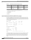
If you insert a single power supply and then set the switch to combined mode, the switch displays
this error message:
Insufficient power supplies present for specified configuration.
This error message also displays in the output for the show power command. This error message
displays because, by definition, combined mode requires that two working power supplies be
installed in your switch.
If the power requirements for the installed modules exceeds the power provided by the power
supplies, the switch displays this error message:
Insufficient power available for the current chassis configuration.
This error message also appears in the show power command output.
If you attempt to insert additional modules into your switch and exceed the power supply, the switch
immediately places the newly inserted module into reset mode, and the switch displays these error
messages:
Module has been inserted
Insufficient power supplies operating.
Additionally, if you power down a functioning switch and insert an additional module or change the
module configuration so that the power requirements exceed the available power, one or more
modules enter reset mode when you power on the switch again.
• The power requirements for the PoE exceed the PoE provided by the power supplies.
If you have too many IP phones drawing power from the system, power to IP phones is cut, and some
phones may be powered down to reduce the power requirements to match the power supplies.
In the first scenario (power requirements exceed the power supplied), the system attempts to resolve this
power usage limitation by evaluating the type and number of modules installed. During the evaluation
cycle, beginning from the bottom of the chassis, the system puts the modules that it is unable to support