


20-13
Software Configuration Guide—Release 15.0(2)SG
OL-23818-01
Chapter 20 Configuring Resilient Ethernet Protocol
Configuring REP
This example shows how to configure the same configuration when the interface has no external REP
neighbor:
Switch# configure terminal
Switch (config)# interface gigabitethernet1/1
Switch (config-if)# rep segment 1 edge no-neighbor primary
Switch (config-if)# rep stcn segment 2-5
Switch (config-if)# rep block port 0009001818D68700 vlan all
Switch (config-if)# rep preempt delay 60
Switch (config-if)# rep lsl-age-timer 6000
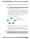
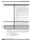
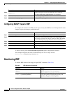
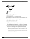
This example shows how to configure the VLAN blocking configuration shown in Figure 20-5. The
alternate port is the neighbor with neighbor offset number 4. After manual preemption, VLANs 100 to
200 are blocked at this port and all other VLANs are blocked at the primary edge port E1 (Gigabit
Ethernet port 1/1).
Switch# configure terminal
Switch (config)# interface gigabitethernet1/1
Switch (config-if)# rep segment 1 edge primary
Switch (config-if)# rep block port 4 vlan 100-200
Switch (config-if)# end
Figure 20-5 Example of VLAN Blocking
Setting Manual Preemption for VLAN Load Balancing
If you do not enter the rep preempt delay seconds interface configuration command on the primary edge
port to configure a preemption time delay, the default is to manually trigger VLAN load balancing on
the segment. Be sure that all other segment configuration has been completed before manually
preempting VLAN load balancing. When you enter the rep preempt segment command, a confirmation
message appears before the command is executed because preemption can cause network disruption.
To manually trigger VLAN load balancing on a segment on the switch that has the segment primary edge
port, perform this task:
E2E1
4
201891
Alternate port (offset 4)
blocks VLANs 100-200
Primary edge port E1
blocks all VLANs except
VLANs 100-200
Command Purpose
Step 1
Switch# configure terminal
Enters global configuration mode.
Step 2
Switch(config)# interface interface-id
Specifies the interface, and enter interface configuration mode.
The interface can be a physical Layer 2 interface or a port
channel (logical interface). The port-channel range is 1 to 48.