


21-12
Software Configuration Guide—Release 15.0(2)SG
OL-23818-01
Chapter 21 Configuring Optional STP Features
Enabling UplinkFast
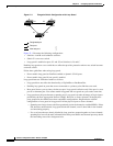
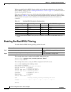
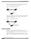
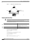
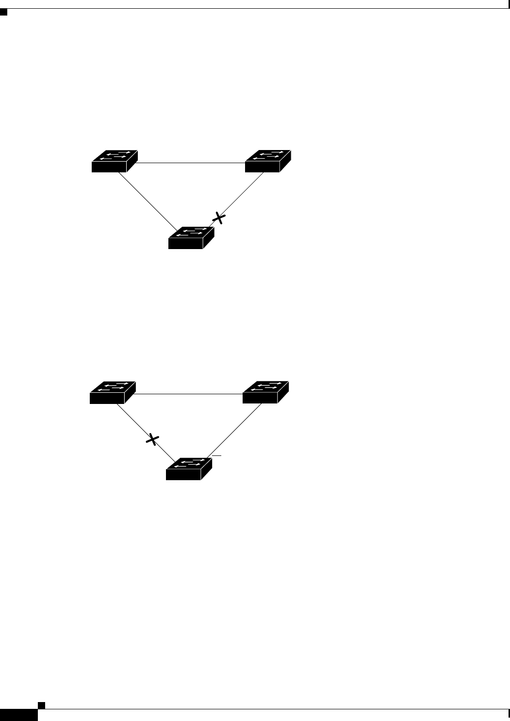
Figure 21-2 shows an example of a topology with no link failures. Switch A, the root switch, is
connected directly to Switch B over link L1 and to Switch C over link L2. The Layer 2 interface on
Switch C that is connected directly to Switch B is in the blocking state.
Figure 21-2 UplinkFast Before Direct Link Failure
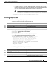
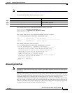
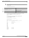
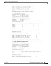
If Switch C detects a link failure on the currently active link L2 on the root port (a direct link failure),
UplinkFast unblocks the blocked port on Switch C and transitions it to the forwarding state without
going through the listening and learning states, as shown in Figure 21-3. This switchover takes
approximately one to five seconds.
Figure 21-3 UplinkFast After Direct Link Failure
Enabling UplinkFast
UplinkFast increases the bridge priority to 49,152 and adds 3000 to the spanning tree port cost of all
interfaces on the switch, making it unlikely that the switch becomes the root switch. The
max_update_rate value represents the number of multicast packets transmitted per second (the default
is 150 packets per second [pps]).
UplinkFast cannot be enabled on VLANs that have been configured for bridge priority. To enable
UplinkFast on a VLAN with bridge priority configured, restore the bridge priority on the VLAN to the
default value by entering a no spanning-tree vlan vlan_ID priority command in global configuration
mode.
L1
L2 L3
Switch C
Switch A
(Root)
Switch B
Blocked port
11241
L1
L2 L3
Switch C
Switch A
(Root)
Switch B
UplinkFast transitions port
directly to forwarding state
Link failure
11242